Permanent magnet synchronous motor (PMSM) with high torque density

A permanent magnet synchronous motor, high torque technology, applied to synchronous motors with stationary armatures and rotating magnets, magnetic circuits, electric components, etc., can solve the problem of reduced output and torque density, and reduced air gap magnetic field waveform area Problems such as small, uneven and symmetrical radial air gaps, to achieve the effect of increasing output and torque density, uniform radial air gaps, and improving air gap magnetic field waveforms

Inactive Publication Date: 2011-08-17
SHANGHAI TOP MOTOR +1
View PDF4 Cites 4 Cited by
  • Summary
  • Abstract
  • Description
  • Claims
  • Application Information

AI Technical Summary

Problems solved by technology

The radial section of the rotor yoke 22 of the existing permanent magnet synchronous motor is circular. In order to reduce torque fluctuations, the outer peripheral surfaces of the permanent magnet poles 23 in the existing permanent magnet synchronous motor are designed as arc surfaces with different axes from the arc axis. , so that the air gap between each permanent magnet pole 23 and the stator gradually increases from the middle to both sides, so that an uneven and symmetrical radial air gap is formed between the stator and rotor. This design can improve the air gap magnetic field waveform , reduce torque ripple and noise, but this design will also reduce the area of ​​the air-gap magnetic field waveform. Since the torque density is proportional to the air-gap magnetic flux density between the stator and rotor, it will cause a decrease in output and torque density

Method used


Image

  • Permanent magnet synchronous motor (PMSM) with high torque density
  • Permanent magnet synchronous motor (PMSM) with high torque density
  • Permanent magnet synchronous motor (PMSM) with high torque density

Examples


Embodiment Construction

[0011] The embodiments of the present invention will be described in further detail below in conjunction with the accompanying drawings, but the present embodiments are not intended to limit the present invention, and any similar structures and similar changes of the present invention should be included in the protection scope of the present invention.

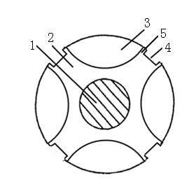
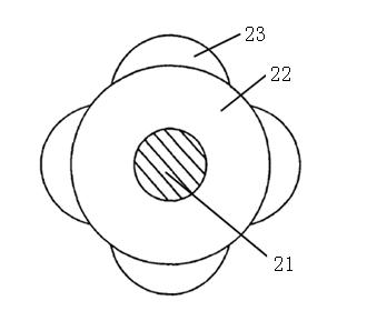
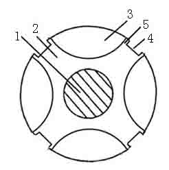
[0012] Such as figure 1 As shown, a high torque density permanent magnet synchronous motor provided by an embodiment of the present invention includes a stator and a rotor, the rotor is coaxially sleeved in the stator, and has an air gap between the stator and the stator; the stator ( (not shown in the figure) includes a stator yoke and a stator winding, the stator yoke is annular, and its inner ring is axially symmetrical with a plurality of stator grooves, and the stator winding is embedded in each stator groove; The rotor includes a rotating shaft 1, a rotor yoke 2 and a plurality of permanent magnetic poles 3, the rotor y...


PUM


Abstract

The invention provides a permanent magnet synchronous motor (PMSM) with high torque density, relating to the technical field of motors and being used for solving the technical problem that the existing motors with low torque ripple are low in torque density and output power. A rotor of the motor comprises a spindle, a rotor yoke and a plurality of permanent magnetic poles, wherein the rotor yoke is fixedly connected with the spindle coaxially; the permanent magnetic poles is fixed on the external surface of the rotor yoke in an axial symmetry mode; the radial sections of the permanent magnetic poles are elliptical, and the external surfaces and inner surfaces of the permanent magnetic poles are both of cambered surfaces; the external surface of the rotor yoke is provided with multiple fixed grooves of magnetic poles in an axial symmetry mode; each permanent magnetic pole is respectively fixed in each fixed groove of the magnetic pole on the external surface of the rotor yoke; the inner surface of each permanent magnetic pole is fitted with the groove bottom and the groove wall of the fixed groove in which the permanent magnetic pole is fixed; edges at the two sides of each permanent magnetic pole are leveled with the notch of the fixed groove in which the permanent magnetic pole is fixed; and the external surface of each permanent magnetic pole and the external surface of the rotor yoke are arranged on the same peripheral surface. The motor provided by the invention is low in the torque ripple and high in the torque density and output power.

Description

technical field [0001] The invention relates to motor technology, in particular to a high torque density permanent magnet synchronous motor technology. Background technique [0002] Such as figure 2 As shown, the rotor of the existing permanent magnet synchronous motor is composed of a coaxially fixed rotating shaft 21, a rotor yoke 22, and a plurality of permanent magnet poles 23 fixed on the outer peripheral surface of the rotor yoke 22 axisymmetrically. The radial section of the rotor yoke 22 of the existing permanent magnet synchronous motor is circular. In order to reduce torque fluctuations, the outer peripheral surfaces of the permanent magnet poles 23 in the existing permanent magnet synchronous motor are designed as arc surfaces with different axes from the arc axis. , so that the air gap between each permanent magnet pole 23 and the stator gradually increases from the middle to both sides, so that an uneven and symmetrical radial air gap is formed between the stat...

Claims


Application Information

Patent Timeline
Patent Type & Authority Applications(China)
IPC IPC(8): H02K21/12H02K1/27
CPCH02K1/278H02K29/03H02K1/2781
Inventor 林德芳
Owner SHANGHAI TOP MOTOR
Why Eureka
Try Eureka