Method for modulating and superposing optical time domain reflectometer (OTDR) testing signals in data transmission optical signals and OTDR testing method

A technology for testing signals and transmitting data, applied in the field of optical communication, can solve the problems of high cost, high equipment price, and high complexity of optical network maintenance, and achieve the effect of reducing complexity, simplifying solutions, and reducing costs

Inactive Publication Date: 2011-08-17
王剑
View PDF3 Cites 24 Cited by
  • Summary
  • Abstract
  • Description
  • Claims
  • Application Information

AI Technical Summary

Problems solved by technology

The optical time domain reflectometer (OTDR) is tested by directly connecting the optical fiber or inserting optical pulses of specific wavelengths into the optical fiber. The test networking scheme is complicated and the price of OTDR equipment is high.
The above factors lead to high complexity and high cost of optical network maintenance with monitoring optical fiber function

Method used


Image

  • Method for modulating and superposing optical time domain reflectometer (OTDR) testing signals in data transmission optical signals and OTDR testing method
  • Method for modulating and superposing optical time domain reflectometer (OTDR) testing signals in data transmission optical signals and OTDR testing method

Examples


Embodiment Construction

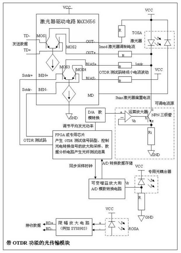
[0014] A specific embodiment of the present invention is an optical transmission module with OTDR function, see figure 1 .

[0015] The optical transmission module with OTDR function includes the following parts: laser and drive circuit, OTDR test signal modulation and superimposed circuit to transmit optical power, optical signal receiving circuit, signal amplification sampling and data analysis circuit for photoelectric conversion, etc. Each part is described in detail below.

[0016] 1. The components of the laser and the driving circuit include: the optical emission sub-module TOSA (including the laser), the bias current control circuit for adjusting the average emission optical power, and the modulation current control circuit for modulating the instantaneous emission optical power. They are described below.

[0017] The laser in the optical emission sub-module TOSA can emit light under the drive of current, and the emitted light power is proportional to the current val...


PUM


Abstract

The invention discloses a method for modulating and superposing optical time domain reflectometer (OTDR) testing signals in data transmission optical signals. In the method, a special digital circuit generates an OTDR testing signal code type, an OTDR testing signal control high-speed current switch produces a slight current change, and the slight current change is superposed to the biased current of a laser, so that transmission optical power is slightly fluctuated according to the change of the OTDR testing signal. An OTDR testing method comprises that: a special optical coupler couples the optical signals scattered or reflected by an optical fiber to be tested for photoelectric conversion and amplification sampling, the transmission attenuation of the optical fiber is calculated by reflection optical power, fluctuation value AC components comprising the signals, reflected by the optical fiber, of an OTDR testing signal source are extracted from sampling data according to the clock frequency of the OTDR testing signal source, the reflected testing signals are compared with the OTDR testing signal source for a plurality of times, and a delay between the two groups of signals is calculated, and a distance between corresponding reflecting points can be calculated by the delay to position an optical fiber connecting point, an optical fiber terminal or a breakpoint.

Description

technical field [0001] The invention relates to the optical communication technology, in particular to the testing technology of the optical transmission module and the optical time domain reflectometer in the optical communication. Background technique [0002] At present, there are various types of optical communication networks in the market, such as: passive optical network (PON), synchronous digital hierarchy optical network (SDH), quasi-synchronous digital hierarchy optical network (PDH), dedicated optical network and so on. The nodes in these optical networks are connected by optical fibers. In order to ensure the quality of communication, important optical fiber lines need to be tested and monitored by an optical time domain reflectometer (OTDR). [0003] The English full name of Optical Time Domain Reflectometer (OTDR) is Optical Time Domain Reflectometer. OTDR is a precise optoelectronic integrated instrument made by using Rayleigh scattering and backscattering ...

Claims


Application Information

Patent Timeline
Patent Type & Authority Applications(China)
IPC IPC(8): H04B10/08H04B10/12H04B10/07H04B10/071
Inventor 王健
Owner 王剑
Why Eureka
Try Eureka