
Reflector for illumination device of motor vehicle and manufacturing method

A lighting device and reflector technology, applied in the reflector field, can solve the problems of difficulty, expensive reflector painting, fine structure installation, etc., and achieve the effect of improving performance

Inactive Publication Date: 2011-08-17
HELLA KG HUECK & CO
View PDF6 Cites 5 Cited by
  • Summary
  • Abstract
  • Description
  • Claims
  • Application Information

AI Technical Summary

Problems solved by technology

[0005] The disadvantage here is that the inside of the reflector is expensive to paint and it is difficult to apply fine structures to the reflective surface

Method used


Image

  • Reflector for illumination device of motor vehicle and manufacturing method
  • Reflector for illumination device of motor vehicle and manufacturing method
  • Reflector for illumination device of motor vehicle and manufacturing method

Examples


Embodiment Construction

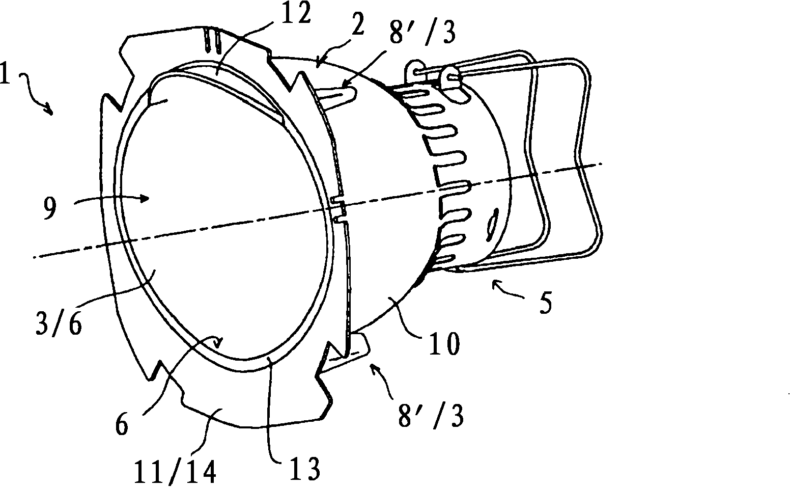
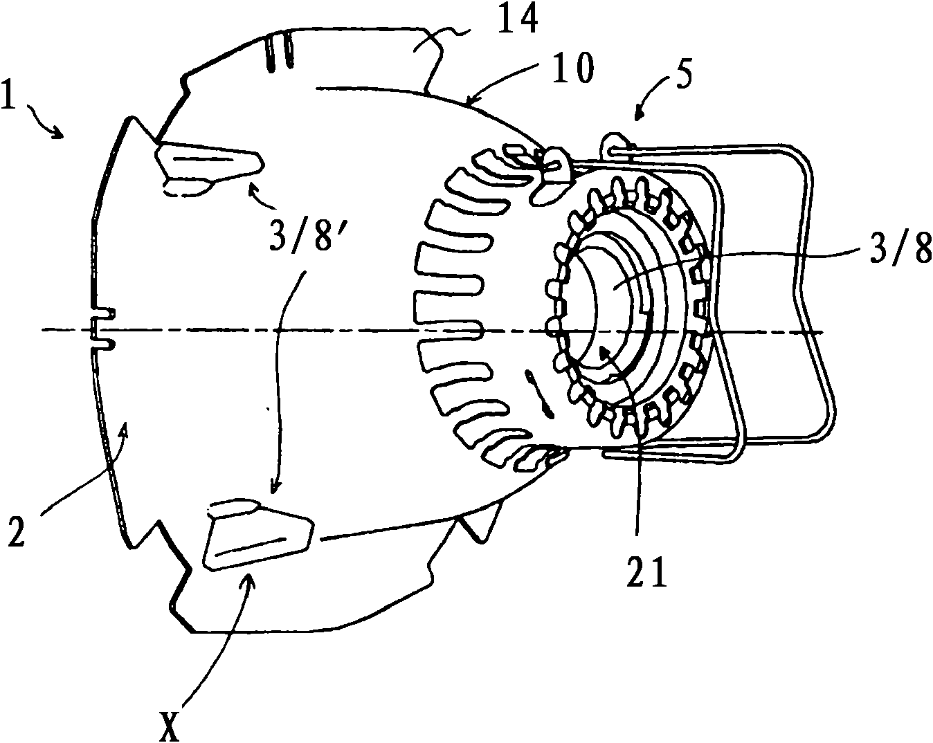
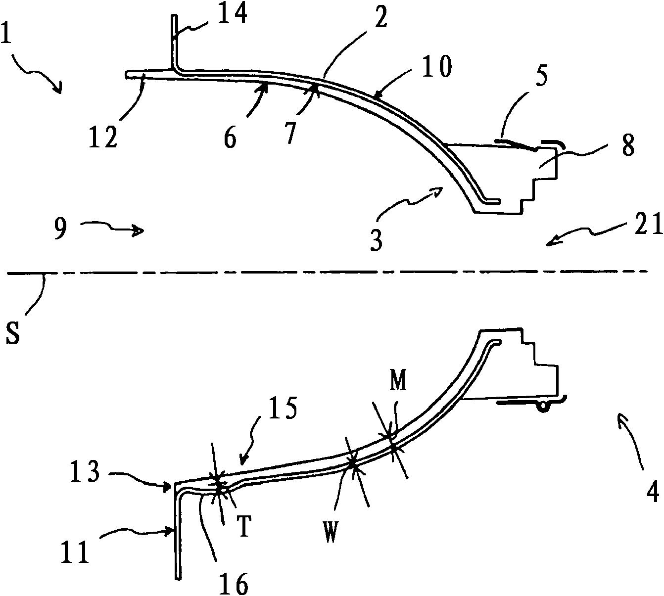
[0026] The reflector 1 for the lighting device of the automobile mainly comprises a bowl-shaped base body 2, an injection molding element 3 applied on the bowl-shaped base body 2, and a support 5 for a lamp, said support being mounted on a lamp holder of the base body Compatible with base body 2 in zone 4. The injection-molded element 3 forms a reflective surface 6 which is applied in a planar manner to the inner side 7 of the base body 2 . The lighting device can be designed as a headlight or as a signal light.

[0027] In addition to the reflective surface 6 , the injection molded element 3 also has further shaped sections, which are designed as connecting sections 8 , 8 ′ for connecting the reflector 1 to other functional components not shown. In the socket region 4 of the reflector 1 , the connecting section 8 is formed forming the opening 21 in such a way that a light source (not shown) can be positioned precisely and coaxially with the base body 2 and held on the reflec...


PUM


Abstract

The invention relates to a reflector for an illumination device of a motor vehicle, comprising a reflection surface and a cup-shaped metallic base member supporting the reflection surface, wherein the reflection surface is attached to an inside of the base member, wherein at least the reflection surface of the reflector is formed from an injection molded element attached to the metallic base member of the reflector, said injection molded element being made of a synthetic material, and wherein the metallic base member is formed in such a way that the attached injection molded element is connected rigidly to the metallic base member.

Description

technical field [0001] The invention relates to a reflector for a lighting device of a motor vehicle, which has a reflective surface and a bowl-shaped metallic base body supporting the reflective surface, wherein the reflective surface is arranged on the inner side of the basic body. [0002] Furthermore, the invention relates to a method for producing the reflector, in which a metallic base body is formed, and to a device for carrying out the method. Background technique [0003] It is known to form metal reflectors for automotive lighting fixtures from sheet metal or by means of die-casting methods. In order to produce a smooth surface, the inside of the metal reflector is coated with a smooth varnish. In order to form the reflective surface, the lacquer layer formed in this way is finally vapor-deposited. [0004] Furthermore, it is known from the subsequent published German patent application 10 2007 017 079.5 that reflectors for automotive lighting fixtures have a met...

Claims


Application Information

Patent Timeline
IPC IPC(8): F21V7/22B29C45/14F21W101/10
CPCB29C45/14311F21S48/1394F21V7/22B29K2705/00B29C45/14221B29C2045/14327B29L2011/0083F21S41/37F21V7/24F21V7/28
Inventor G·勒特格里B·德林
Owner HELLA KG HUECK & CO
Learn More