Engine exhaust system and method

An exhaust system and engine technology, applied in engine components, combustion engines, engine control, etc., can solve problems such as affecting the efficiency of the exhaust treatment system and reducing the quality of exhaust emissions

Inactive Publication Date: 2015-09-02
FORD GLOBAL TECH LLC
View PDF6 Cites 0 Cited by
  • Summary
  • Abstract
  • Description
  • Claims
  • Application Information

AI Technical Summary

Problems solved by technology

Restricted flow characteristics can also affect the efficiency of exhaust treatment systems, reducing the quality of exhaust emissions

Method used


Image

  • Engine exhaust system and method
  • Engine exhaust system and method
  • Engine exhaust system and method

Examples


Embodiment Construction

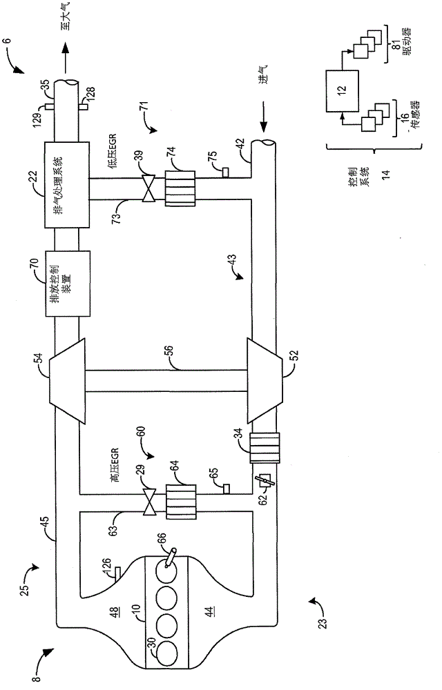
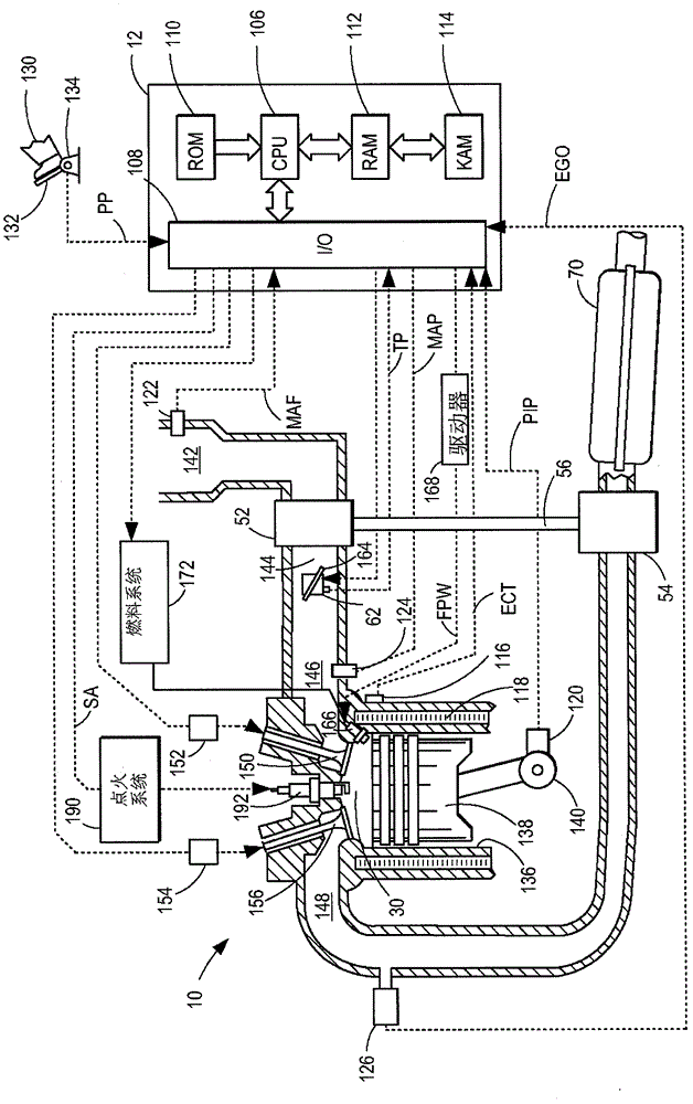
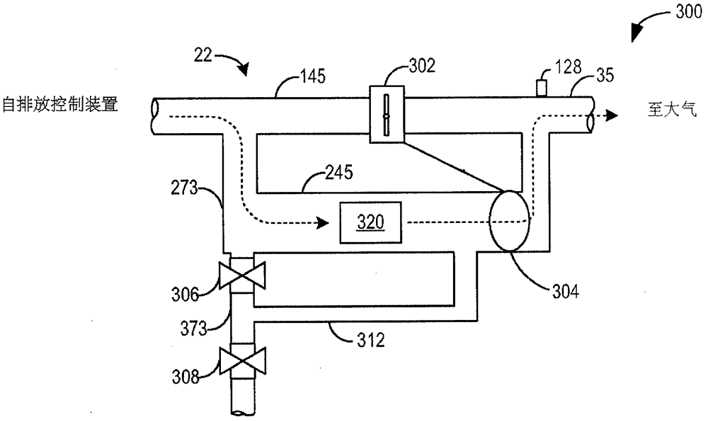
[0027] The following description relates to systems and methods for operating an exhaust treatment system associated with an internal combustion engine to remove hydrocarbons from exhaust emissions. For example, exhaust gas treatment systems are available for diesel engines equipped with exhaust gas temperature coolers. like figure 1 As shown, by coupling the operation of the engine's exhaust treatment system with the low pressure EGR system, advantageous synergy may be obtained. like Figure 3-5 As shown in , by coordinating the opening of the exhaust gas treatment system valve with the EGR valve of the EGR system, cold start exhaust HC can be effectively captured for subsequent reaction or can be recycled into the engine intake system. The exhaust treatment system may include an integrated exhaust valve system including an exhaust valve connected to the isolation valve ( Figures 6A-6K ). Exhaust valve systems can be arranged so that the opening of one valve is linked to...


PUM


Abstract

Systems and methods are provided for operating an engine exhaust system. In one example, a system comprises a first valve, and a second valve coupled to the first valve via a shaft. A first position of the shaft situates the first valve closed and the second valve open, a second position situates the second valve closed and the first valve open by a first amount, and a third position situates the second valve closed and the first valve open by a second, larger amount.

Description

【Technical field】 [0001] The present invention generally relates to exhaust systems and methods for internal combustion engines configured to capture hydrocarbon emissions. 【Background technique】 [0002] Engine exhaust systems utilize hydrocarbon retention devices, such as hydrocarbon (HC) traps, to retain cold start emissions (HC storage). The retained HC can be re-reacted at a later time (eg after the exhaust gas temperature has become sufficiently warm) or recirculated into the engine intake system (HC purging). The engine exhaust system may also be connected to an engine exhaust gas recirculation (EGR) system, where EGR flow is used to draw stored HC from the HC trap. For example, one or more exhaust valves may be used to regulate the amount and direction of exhaust flow through the exhaust treatment system based on whether storage or purge operation of the HC trap is desired, or whether EGR operation is desired. One or more exhaust valves can be integrated such that ...

Claims


Application Information

Patent Timeline
Patent Type & Authority Patents(China)
IPC IPC(8): F02D9/08F01N9/00F01N3/02F02D21/08F02M25/07
CPCF02M25/0719F02M25/0709F02D41/0065F02M25/0707Y02T10/47Y02T10/20F01N2410/00F02D9/04F02M25/0713F01N3/0835F02M25/0718F02B29/0406F02M25/0732F02M25/0754F02D9/1055F02M26/05F02M26/06F02M26/10F02M26/15F02M26/16F02M26/24F02M26/47Y02T10/12Y02T10/40
Inventor J·A·卢佩斯库D·J·斯泰爱滋J·M·克恩斯M·J·于里克S·B·史密斯D·A·梅
Owner FORD GLOBAL TECH LLC
Why Eureka
Try Eureka