
Diversion plate used for acoustic wave soot blower

A technology of sonic sootblower and deflector, which is applied in the treatment of combustion products, combustion methods, and removal of solid residues, etc. problem, to achieve the effect of improving the use effect and increasing the effective area

Inactive Publication Date: 2011-08-24
上海恒纽科技发展有限公司
View PDF6 Cites 4 Cited by
  • Summary
  • Abstract
  • Description
  • Claims
  • Application Information

AI Technical Summary

Problems solved by technology

However, the current way of sonic sootblower to compress air and sound waves into the boiler is the direct blowing method, because the diameter of the blown horn tube is limited, so that the sound wave acts on the boiler tube wall soot blowing effect area is small, resulting in the sound wave sootblower. Poor use

Method used


Image

  • Diversion plate used for acoustic wave soot blower
  • Diversion plate used for acoustic wave soot blower
  • Diversion plate used for acoustic wave soot blower

Examples


Embodiment Construction

[0015] In order to make the technical means, creative features, goals and effects achieved by the present invention easy to understand, the present invention will be further described below in conjunction with specific illustrations.

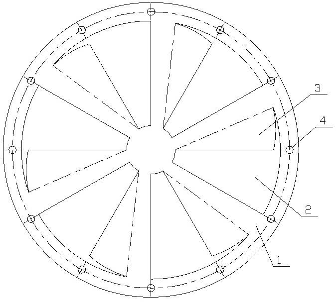
[0016] see figure 1 , a deflector for a sonic soot blower is a circular deflector 1, and the thickness of the circular deflector 1 is 2 mm to 4 mm. A plurality of fan-shaped guide holes 2 are evenly processed on the circular guide plate 1 along the circumference. Because the sonic soot blower is used in boilers, the circular guide plate 1 is made of high temperature resistant, wear-resistant, corrosion-resistant, Stainless steel. Of course, according to the size of the horn of the sonic soot blower, the present invention can also set the number of fan-shaped guide holes 2 to 5 or more than 6 according to the actual situation.

[0017] The sides of each fan-shaped flow guide hole 2 in the same direction are provided with guide vanes 3, and the ...


PUM


Abstract

The present invention discloses a diversion plate used for an acoustic wave soot blower. The guide plate is characterized in that a circular guide plate is included, fan-shaped diversion holes are arranged on the upper circumference of the circular guide plate, diversion blades are arranged on the same side of every fan-shaped diversion hole, and the included angle between the diversion surface of the diversion blade and the through-flow surface of a fan-shaped diversion hole is more than 10 degrees and less than 60 degrees. The diversion plate has the advantages that, after being diverted by the diversion blades arranged on the side of every fan-shaped diversion hole, compressed air and acoustic wave are blown out in the tangential direction of the fan-shaped diversion hole to form a whirlpool shape, thus the effective soot blowing area is greatly increased and the use effect of the acoustic wave soot blower is consequently increased.

Description

technical field [0001] The invention relates to the technical field of sonic soot blowers, in particular to a deflector for sonic soot blowers. Background technique [0002] During the production and operation of the boiler, ash and slagging on the heating area of ​​its water wall, superheater, economizer, preheater and flue, etc., have long plagued production and are difficult to solve. It not only weakens the heat transfer of the heating surface of these equipment, resulting in lower thermal efficiency and reduced production load, but also may lead to unexpected shutdown of the furnace when the heating area is seriously ash and slagging, resulting in major economic losses. Therefore, traditional boilers are equipped with soot blowers, such as steam soot blowers, compressed air soot blowers, steel ball soot blowers, etc., but in terms of operation and performance, these soot blowers have limited soot blowing range, soot blowing There are disadvantages such as dead angles, ...

Claims


Application Information

Patent Timeline
IPC IPC(8): F23J1/00F23J3/00B23P15/00
Inventor 谢立忠顾惠松
Owner 上海恒纽科技发展有限公司
Learn More