
Array infrared thermometer

An infrared thermometer, array technology, applied in the direction of instruments, electric radiation detectors, signal transmission systems, etc., can solve the problems of high price, inability to collect and analyze temperature information in real time, and inability to reflect the temperature distribution of the measured object, etc., to achieve The effect of improving the analysis effect

Inactive Publication Date: 2011-08-24
TIANJIN UNIVERSITY OF TECHNOLOGY
View PDF3 Cites 19 Cited by
  • Summary
  • Abstract
  • Description
  • Claims
  • Application Information

AI Technical Summary

Problems solved by technology

[0002] In the process of modern industrial production, in order to ensure the normal operation of process equipment and ensure that the production environment is within the required ambient temperature range, it is often necessary to monitor the temperature of process equipment and products. Information is collected, but the infrared thermometer can only measure the average temperature value of a small area of ​​the measured object each time, and cannot reflect the overall temperature distribution of the measured object, thus greatly reducing the effect of infrared temperature analysis, and cannot The temperature information of the entire surface of the object is collected and analyzed in real time, and the infrared thermal imager can do this, but because the infrared thermal imager uses the ambient temperature to calibrate, the measurement error of the object in the high temperature section is relatively large, and it can only Displays the relative temperature of each point of the measured object, cannot accurately reflect the absolute value of the temperature of each point, and is expensive

Method used


Image

  • Array infrared thermometer
  • Array infrared thermometer
  • Array infrared thermometer

Examples


Embodiment Construction

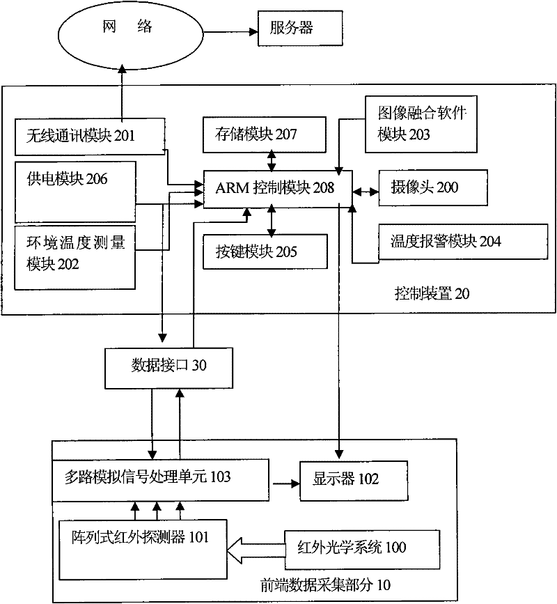
[0021] The array infrared thermometer of the present invention adopts a high-performance arrayed polysilicon material detector, which can measure the two-dimensional temperature field on the surface of an object, and combines image synchronous acquisition technology, visual image fusion technology, embedded intelligent analysis technology, Data stream wireless upload technology, so that users can remotely monitor the collected information and processed results in different places at the first time.

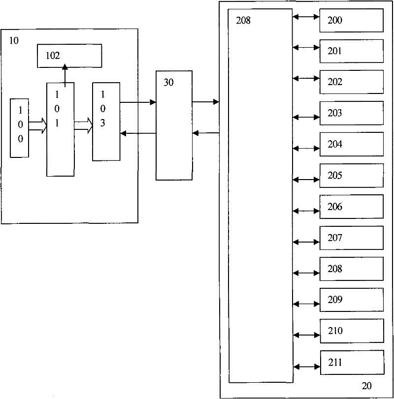
[0022] see figure 1 As shown in , the array infrared thermometer in the present invention includes a front-end data acquisition part 10 , a control device 20 , and a data interface 30 connecting the front-end data acquisition part 10 and the control device 20 . Wherein, the front-end data acquisition part 10 includes an infrared optical system 100, an arrayed infrared detector 101, a display screen 102, and a multi-channel signal processing unit 103 connected to and processing the...


PUM


Abstract

The invention provides an array infrared thermometer belonging to the field of non-contact infrared thermometry and image processing. The thermometer comprises a front data acquiring part, a control device and a data interface connected between the front data acquiring part and the control device, wherein the front data acquiring part comprises an infrared optical system, an array infrared detector and the like; and the control device comprises a camera, a wireless communication module, an ambient temperature measurement module, an image fusion software module, a temperature alarm module, a button module, a power supply module, a memory module and the like. The array infrared thermometer can measure the temperature distribution condition on the surface of an object in real time, simultaneously ensure infrared temperature distribution of the object to correspond to the measured object, display the real-time variation condition of the temperature of the measured object and directly measure the actual temperature of the measured object through real-time calibration, thus greatly improving the analysis effect of monitoring the infrared temperature on the surface of the object.

Description

technical field [0001] The invention belongs to the field of non-contact infrared temperature measurement and image processing, and in particular relates to an area array infrared thermometer for measuring high-temperature sections. Background technique [0002] In the process of modern industrial production, in order to ensure the normal operation of process equipment and ensure that the production environment is within the required ambient temperature range, it is often necessary to monitor the temperature of process equipment and products. Information is collected, but the infrared thermometer can only measure the average temperature value of a small area of ​​the measured object each time, and cannot reflect the overall temperature distribution of the measured object, thus greatly reducing the effect of infrared temperature analysis, and cannot The temperature information of the entire surface of the object is collected and analyzed in real time, and the infrared thermal...

Claims


Application Information

Patent Timeline
IPC IPC(8): G01J5/10G08C17/02
Inventor 魏臻姜啸宇钟声张岷樊秀梅闫富荣王树雨张海伟郭富赵圣
Owner TIANJIN UNIVERSITY OF TECHNOLOGY
Learn More