Light emitting diode (LED) packaging process

A technology of LED packaging and LED brackets, which is applied to electrical components, circuits, semiconductor devices, etc., can solve the problems of low color rendering index, poor color rendering, and the color of white light tubes is not soft enough, so as to improve the color rendering and area. small effect

Inactive Publication Date: 2011-08-24
WEIFANG GUANGSHENG NEW ENERGY
View PDF3 Cites 10 Cited by
  • Summary
  • Abstract
  • Description
  • Claims
  • Application Information

AI Technical Summary

Problems solved by technology

Because it is difficult to effectively control the color temperature with a single YAG phosphor, the color of the sealed white light tube is not soft enough, the color rendering is not good, and the color rendering index is low (usually between 50-80), whi

Method used


Image

  • Light emitting diode (LED) packaging process
  • Light emitting diode (LED) packaging process
  • Light emitting diode (LED) packaging process

Examples


Embodiment 1

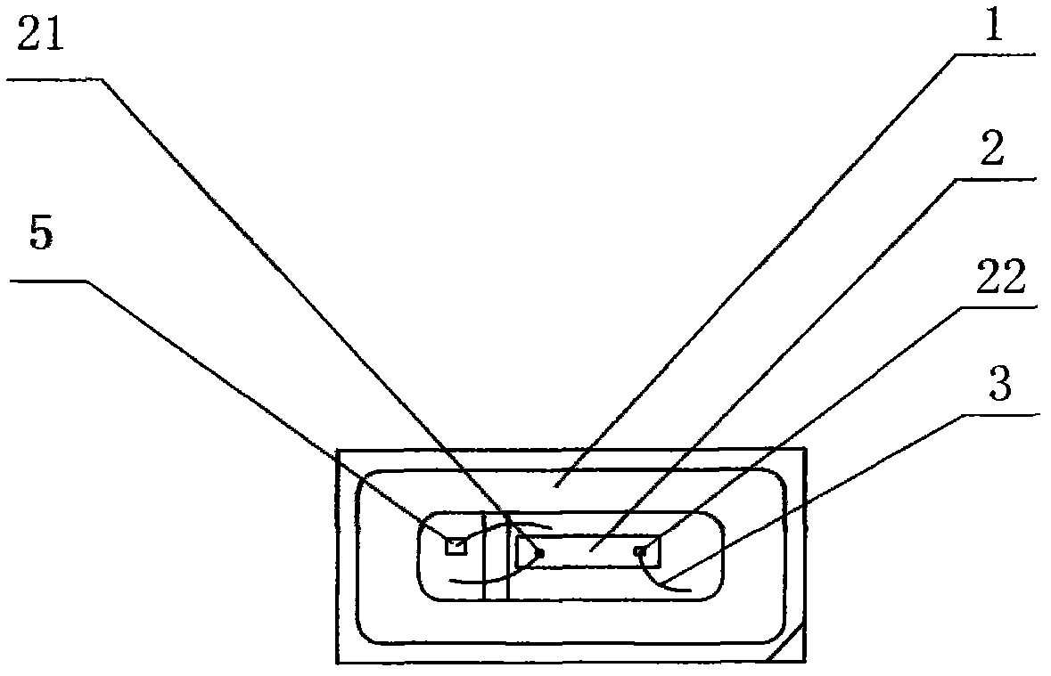
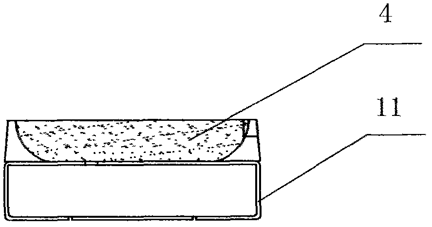
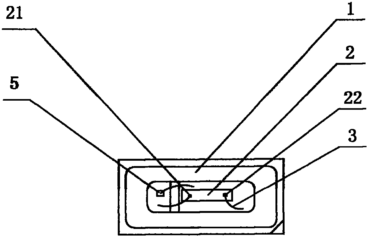
[0019] Such as figure 1 , figure 2 Commonly shown, an LED packaging process includes the following steps: (1) provide an LED bracket 1, and the material of the LED bracket 1 is white PPA plastic. Since the thermal deformation temperature of PPA plastic is as high as 300°C and the continuous use temperature can reach 170°C, it can maintain its superior mechanical properties such as strength, hardness, fatigue resistance and anti-fatigue in a wide temperature range and high humidity environment Creep resistance, which can meet the short-term and long-term heat resistance required by LED brackets. In this embodiment, the material of the LED bracket electrode 11 and the bottom of the cooling cup is C194 lead frame copper strip, which belongs to Cu-Fe-P copper alloy, has high strength, high electrical conductivity, high thermal conductivity, and good Excellent properties such as weldability, wettability, plastic sealing, and oxidation resistance.

[0020] (2) Solid crystal: fir...

Embodiment 2

[0026] Embodiment 2 is basically the same as Embodiment 1, except that the fluorescent glue is prepared from the following raw materials in parts by weight: nitride red phosphor TMR-500630-254530, 7; high-power phosphor HY-Y805, 93; green phosphor TMG-300520, 5; transparent silicone 8670, 1000.

Embodiment 3

[0028] Embodiment 3 is basically the same as Embodiment 1, except that the fluorescent glue is prepared from the following raw materials in parts by weight: nitride red phosphor TMR-500630-254530, 10; high-power phosphor HY-Y805, 95; green phosphor TMG-300520, 2; transparent silicone 8670, 1000.

[0029] Since the fluorescent glue of the present invention is based on the high-power fluorescent powder HY-Y805, the high-color-rendering nitride red phosphor TMR-500630-254530 and the green fluorescent powder TMG-300520 are added, and the prepared fluorescent glue can be Make up for the defects of various colors of light, make the final white light closer to sunlight, improve the color rendering, and the color rendering index can be increased to 95, making the white light more comfortable and soft. The white light LED obtained after packaging has a small area of ​​only 4.2 square millimeters. It satisfies people's requirements for short, light and thin white light sources.


PUM


Abstract

The invention discloses a light emitting diode (LED) packaging process, which mainly comprises the following steps of: performing die bond, bonding, and applying fluorescent glue, wherein the fluorescent glue is prepared from the following raw materials in part by weight: 5 to 10 parts of nitride red fluorescent powder TMR-500630-254530, 90 to 95 parts of high-power fluorescent powder HY-Y805, 2 to 5 parts of green fluorescent powder TMG-300520 and 1,000 parts of transparent organic silica gel 8670. The fluorescent glue is prepared by adding the high-color rendering property nitride red fluorescent powder TMR-500630-254530 and the green fluorescent powder TMG-300520 on the basis of the high-power fluorescent powder HY-Y805, and the prepared fluorescent glue can overcome defects of light in various colors, so that the finally obtained white light is closer to sunlight, the color rendering properties are improved, and the color rendering index can be improved to 95. Therefore, the white light is more comfortable and softer, the packaged white LED has a small area of only 4.2 square millimeters, and the requirement of people on a short, thin and light white light source is met.

Description

technical field [0001] The invention relates to the technical field of semiconductor devices, in particular to an LED packaging process. Background technique [0002] The usual white light is to coat the blue light chip with YAG phosphor powder, and use the blue light LED to irradiate the fluorescent material to produce yellow light complementary to the blue light, and then mix the complementary yellow light and blue light to obtain the white light required by the naked eye , thus making white LED. Because it is difficult to effectively control the color temperature with a single YAG phosphor, the color of the sealed white light tube is not soft enough, the color rendering is not good, and the color rendering index is low (usually between 50-80), which is difficult to meet the market's high color rendering requirements; In addition, the current lighting single lamp area is larger than 20 square millimeters, which is difficult to meet people's requirements for short, light a...

Claims


Application Information

Patent Timeline
IPC IPC(8): H01L33/00H01L33/48H01L33/50
Inventor 李玉芝吉爱华
Owner WEIFANG GUANGSHENG NEW ENERGY
Why Eureka
Try Eureka