Hydraulic drive device for construction machine

A driving device, engineering machinery technology, applied in the direction of fluid pressure actuating device, mechanical equipment, fluid pressure actuating system components, etc., can solve problems such as control instability, achieve good startability, reduce the load of hydraulic pumps, avoid The effect of response delay

Active Publication Date: 2011-08-24
NIHON KENKI CO LTD
View PDF9 Cites 16 Cited by
  • Summary
  • Abstract
  • Description
  • Claims
  • Application Information

AI Technical Summary

Problems solved by technology

At this time, if the unloading valve is maintained with high responsiveness, its control will be unstable, and it will develop into a vibration state (so-called chattering)

Method used


Image

  • Hydraulic drive device for construction machine
  • Hydraulic drive device for construction machine
  • Hydraulic drive device for construction machine

Examples


Embodiment Construction

[0034] Embodiments of the present invention will be described below using the drawings.

[0035] ~Structure~

[0036]

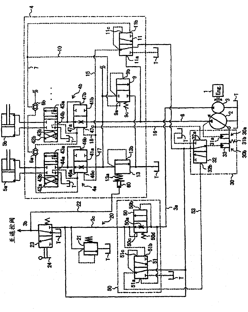
[0037] figure 1 It is a hydraulic circuit diagram showing the hydraulic drive device of one embodiment of the present invention.

[0038] exist figure 1 Among them, the hydraulic drive device of the present embodiment includes: an engine 1; a variable displacement hydraulic pump 2 and a fixed displacement pilot pump 3 as a master pump driven by the engine 1; a control valve 4; a slave hydraulic pump 2. The discharged pressurized oil is guided through the control valve 4, and passes through a plurality of actuators 5a, 5b, . . . driven by the pressurized oil.

[0039] The control valve 4 has: a plurality of valve members 4a, 4b, . A plurality of pressure compensating valves 41a, 41b, ... and a plurality of flow control valves (main spool valves) 42a, 42b, ... for separately controlling the flow (flow rate and direction) of pressure oil; Shuttle spool val...


PUM


Abstract

The invention provides a hydraulic drive device for construction machine. A main relief valve (13) is provided with an urging force changing device (60). The urging force changing device (60) forms, together with a gate lock valve (23) and a gate lock lever (24), a relief-set-pressure changing means capable of switching, by means of manual operation, the set pressure of the main relief valve (13) between a normal first pressure (25 MPa, for example) and a second pressure (3.0 MPa, for example) which is lower than the first pressure and which enables, together with an unload valve (9), oil discharged from a hydraulic pump (2) to be returned to a tank (T) when the ambient temperature is below the freezing point and actuators (5a, 5b,...) are not driven. The structure reduces a load on the hydraulic pump in a cold start of an engine without sacrificing anti-hunting characteristics of the unload valve, and this allows the engine to be started more easily at low temperatures.

Description

technical field [0001] The present invention relates to a hydraulic drive device for construction machinery such as a hydraulic excavator, and more particularly to a hydraulic drive device that performs load sensing control such that the discharge pressure of a hydraulic pump is higher than the maximum load pressure of a plurality of actuators by a target pressure difference. Background technique [0002] As such a hydraulic drive device, there is an invention described in Patent Document 1, for example. In the hydraulic drive device described in Patent Document 1, a main relief valve and an unloading valve are connected to a hydraulic supply circuit that guides discharge oil from a hydraulic pump (main pump). The main relief valve is a safety valve. When the flow control valve operates, the load pressure of the actuator is relatively high, and the pressure of the hydraulic supply circuit (discharge pressure of the hydraulic pump) reaches the relief set pressure (for example...

Claims


Application Information

Patent Timeline
Patent Type & Authority Applications(China)
IPC IPC(8): F15B11/00E02F9/22F15B21/04
CPCF15B2211/30535F15B11/165F15B2211/50536F15B2211/50518F15B2211/253F15B11/163E02F9/2232E02F9/2285F15B2211/20546E02F9/2225E02F9/2296
Inventor 高桥究钓贺靖贵竹林圭文森和繁
Owner NIHON KENKI CO LTD
Why Eureka
Try Eureka