Clamping device

A technology of clamping device and clamping arm, which is applied in the direction of casting molding equipment, metal processing equipment, manufacturing tools, etc., can solve the problems of no clamping device, etc., achieve the effects of simple structure, avoiding sand core falling off, and improving production efficiency

Inactive Publication Date: 2011-08-31
SUZHOU SUZHU FOUNDRY MACHINERY MFG
View PDF5 Cites 13 Cited by
  • Summary
  • Abstract
  • Description
  • Claims
  • Application Information

AI Technical Summary

Problems solved by technology

[0003] In foundry production, after the cold box core shooter shoots the sand cores, it is necessary to dip-coat the surface of the sand cores, etc., but because many sand cores are large in size, it is difficult to do it manually. Therefore, for the larger sand cores

Method used


Image

  • Clamping device
  • Clamping device

Examples


Embodiment Construction

[0011] Preferred embodiments of the present invention will be described in detail below in conjunction with the accompanying drawings.

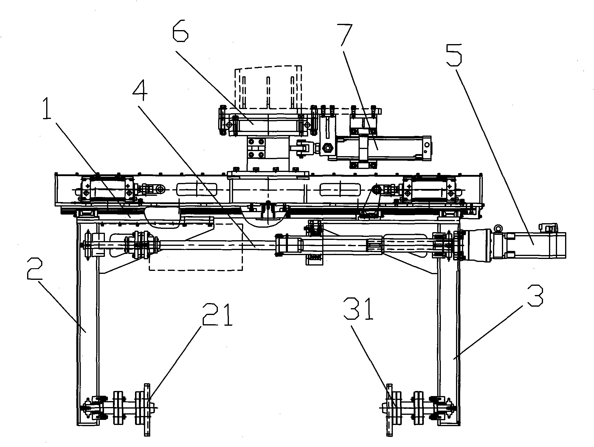
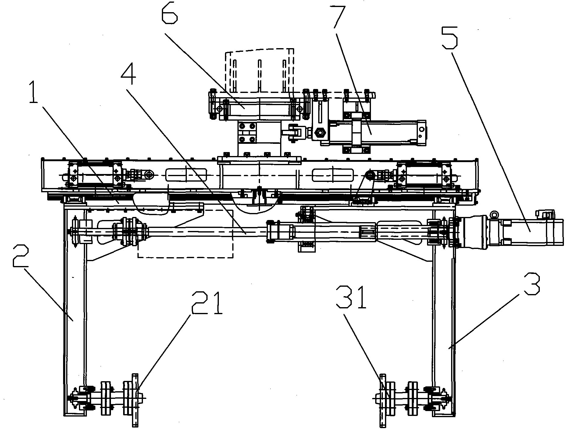
[0012] Such as figure 1 As shown, the clamping device includes a supporting frame 1, on which a fixed clamping arm 2 and a movable clamping arm 3 are arranged, the lower end of the fixed clamping arm 2 is provided with a splint 21, and the movable clamping arm The lower end of 3 is provided with a splint 31, and splint 21,31 is opposite. The fixed clamping arm 2 is fixed on the supporting frame 1, the movable clamping arm 3 is connected with the screw rod 4 through a moving nut, the screw rod 4 is connected with the driving motor 5, and the screw rod 4 and the driving motor 5 are installed on the supporting frame 1. The driving motor 5 drives the screw rod 4 to rotate, and then the nut drives the moving clamping arm 3 to move back and forth on the screw rod 4 . A slewing support bracket 6 is also arranged on the support frame 1 , and the su...


PUM


Abstract

The invention discloses a clamping device which comprises a supporting frame, the supporting frame is provided with a fixed clamping arm and a movable clamping arm, the lower ends of the fixed clamping arm and the movable clamping arm are respectively provided with a clamp plate, and the two clamp plates are arranged opposite to each other; and the fixed clamping arm is fixed at the supporting frame, the movable clamping arm is connected with a screw rod by a movable nut, the screw rod is connected with a drive motor, and the drive motor drives the screw rod to rotate. The clamping device disclosed by the invention has the advantages of simple structure and capability of realizing the automated clamping of sand cores, is easy to use, effectively improves the production efficiency, reduces the labor intensity, and effectively avoids the falling-off of sand cores in the process of coating the sand cores with paints by robots.

Description

technical field [0001] The invention relates to the casting field, in particular to a clamping device for clamping a mud core when the mud core is dipped and coated with paint. Background technique [0002] In the modern casting production process, in order to improve the casting efficiency and meet the requirements of modern production, most of the cores used in the casting process are manufactured by cold box core shooters, which are widely used in the foundry machinery industry. The core made by the cold box core shooter has the advantages of accurate size and smooth surface, so it is widely used in many foundry companies. [0003] In foundry production, after the cold box core shooter shoots the sand cores, it is necessary to dip-coat the surface of the sand cores, etc., but because many sand cores are large in size, it is difficult to do it manually. Therefore, for the larger sand cores, it is necessary to use a robot to complete the action. When the robot moves, a cla...

Claims


Application Information

Patent Timeline
IPC IPC(8): B22C23/02
Inventor 王玉南
Owner SUZHOU SUZHU FOUNDRY MACHINERY MFG
Why Eureka
Try Eureka