Image forming device

A technology of image and nozzle, applied in the direction of power transmission device, printing, transfer materials, etc., can solve the problems of recording head position deviation, position deviation, intense vibration of printing car, etc., and achieve the effect of inhibiting wear

Inactive Publication Date: 2014-09-24
RICOH KK
View PDF10 Cites 0 Cited by
  • Summary
  • Abstract
  • Description
  • Claims
  • Application Information

AI Technical Summary

Problems solved by technology

[0009] (1) However, the printing car has the characteristics of intense vibration when printing
On the other hand, in the technique of (A) above, in order to rotate and adjust the eccentric cam, the camshaft needs to have a gap for rotation at its front and part, and the positional deviation of the recording head is caused by shaking between the gaps. may affect image quality
[0010] (2) In the technique of (B) above, by the friction of the tapered surface of the X stopper pressed by the spring between the side end portion of the recording head and the inclined block, the instability of the up and down motion of the X stopper may be caused, Because the position of the recording head will shake with the vibration of recording, it may affect the image quality
However, none of the above (A) and (B) can be applied to "adjust the height direction of the recording head according to the thickness of the printing medium".
[0012] (4) Even if the techniques of (A) and (B) above are applied to the "mechanism for adjusting the height direction of the recording head", the camshaft of the eccentric cam is in the gap of the shaft fitting part due to the lifting and lowering of the recording head Can tilt, causing positional deviation
In addition, due to the repeated lifting action of the recording head, the problem of damage caused by long-term wear caused by friction between the eccentric cam and the object in contact with it should also be considered

Method used


Image

  • Image forming device
  • Image forming device
  • Image forming device

Examples


Embodiment Construction

[0158] Hereinafter, embodiments of the present invention will be described with reference to the drawings. In addition, the same code|symbol is attached|subjected to the structural part which has the same function or the procedure which performs the same process, and the overlapping description is abbreviate|omitted.

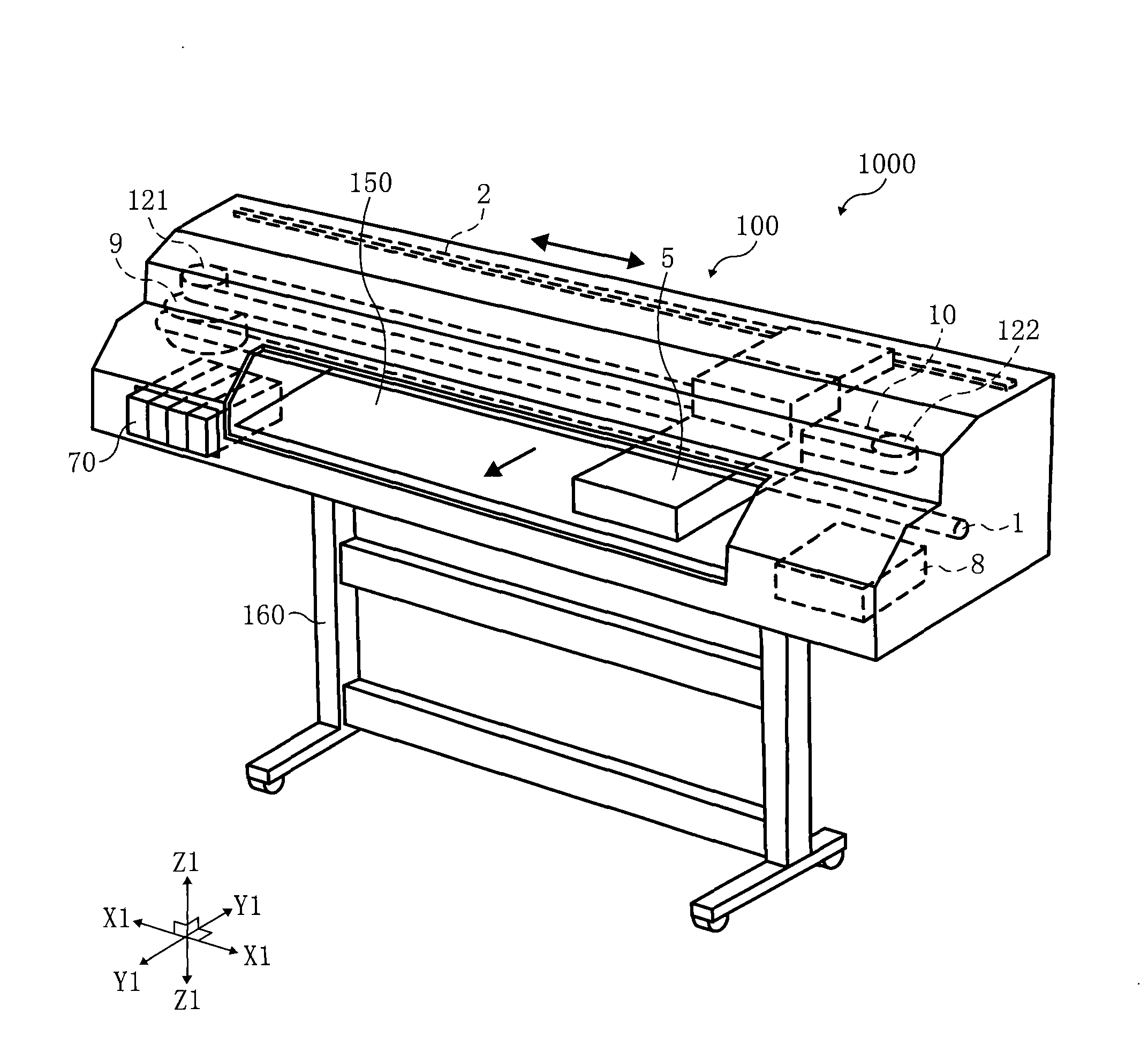
[0159] The image forming apparatus 1000 of this embodiment can be roughly divided into a recording apparatus 100 and a paper feeding unit. The recording device 100 is mainly composed of a mechanism that injects ink into a recording medium (for example, paper) through a recording head by an inkjet method to form an image, and the paper feeding unit is mainly composed of a mechanism that transports the recording medium into the recording device.

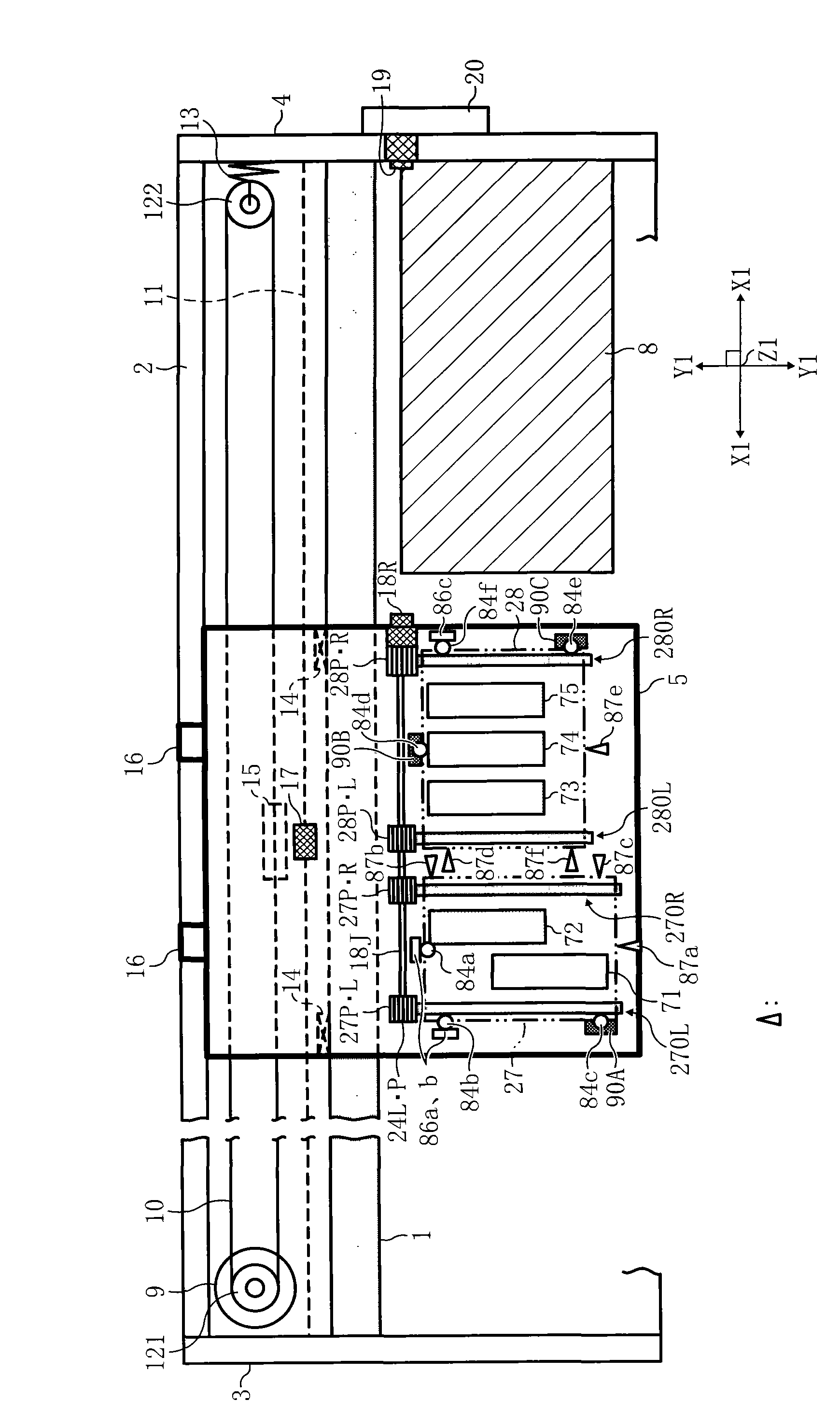
[0160] [Summary of the overall configuration of the recording device]

[0161] A perspective view of the image forming apparatus 1000 and the recording apparatus 100 is shown in figure 1 As shown, a schematic diagram o...


PUM


Abstract

The invention relates to an image forming device, which comprises a nozzle adjusting means capable of adjusting the position relation between a plurality of nozzle retainers keeping multiple record heads and a printing vehicle loaded with the nozzle retainers. Even the nozzle retainers elevate with respect to the printing vehicle, the position of the nozzle retainers in a horizontal direction can also be maintained. Through the nozzle adjusting means, the position deviation of the recording head due to the vibration of the nozzle adjusting means can be prevented. In addition, the wearing of the nozzle adjusting means due to the repetitive elevation of the recording head can be prevented. A middle component (91) disposed between a contacting part (84c) of the nozzle retainer (27) and the nozzle adjusting means (90A) is a plate spring enabling the nozzle adjusting means (90A).

Description

technical field [0001] The present invention relates to an image forming apparatus using an inkjet system such as a printer, a copier, and a facsimile. Background technique [0002] In the existing image forming apparatus using the inkjet method, the printing medium is conveyed intermittently in the sub-scanning direction, and during the stay of the printing medium, the printing carriage with a plurality of recording heads is moved perpendicular to the sub-scanning direction. It reciprocates in the main scanning direction, and at the same time, after the ink is ejected into the printing medium through the recording head, an image is formed in the printing medium. [0003] The recording head has a plurality of nozzle rows in which a plurality of nozzles ejecting ink are arranged in a straight line, and in order to obtain a good image, it is very important that the nozzle rows of each recording head in the printing vehicle be located in a positional relationship determined by ...

Claims


Application Information

Patent Timeline
Patent Type & Authority Patents(China)
IPC IPC(8): B41J2/01B41J25/304
Inventor 杂贺聪一小室一郎成濑慎一郎赖本卫间濑隆介
Owner RICOH KK
Why Eureka
Try Eureka