Method and apparatus of improving recovery efficiency of shale gas through a blast mode

A shale gas and recovery factor technology, applied in earth-moving drilling, fluid production, wellbore/well components, etc., can solve the problems of slow fracturing fluid backflow, fracturing fluid leakage, and large formation damage. Effects of increasing range, increasing total surface area, increasing resolution rate

Active Publication Date: 2011-08-31
INST OF MECHANICS - CHINESE ACAD OF SCI
View PDF5 Cites 19 Cited by
  • Summary
  • Abstract
  • Description
  • Claims
  • Application Information

AI Technical Summary

Problems solved by technology

Both the hydraulic fracturing method and the foam fracturing method have insurmountable shortcomings in the fracturing process of shale formations: first, the fracturing fluid is equipped with a lar

Method used


Image

  • Method and apparatus of improving recovery efficiency of shale gas through a blast mode
  • Method and apparatus of improving recovery efficiency of shale gas through a blast mode
  • Method and apparatus of improving recovery efficiency of shale gas through a blast mode

Examples


Embodiment 1

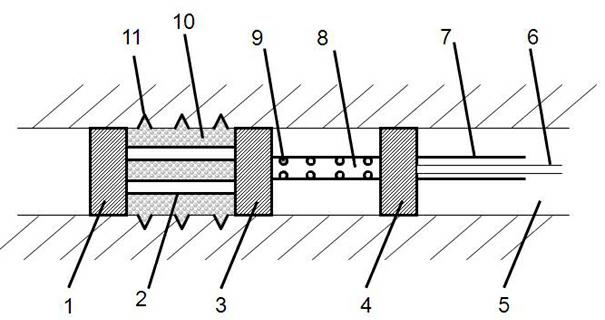
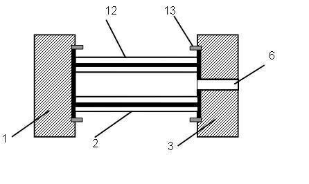
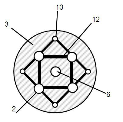
[0022] Such as figure 1 As shown, the device for increasing the recovery rate of shale gas by means of explosion disclosed in the present invention includes a drug injection detonation device and a gas delivery device, wherein the drug delivery detonation device includes: a lower isolation device 1, a high-strength connecting column 2, a middle isolation device Device 3, drug delivery tube 6, detonation circuit 12 and detonation device 13. The gas conveying device includes: middle isolating device 3 , upper isolating device 4 , oil and gas pipe 7 , and perforated air intake pipe 8 .

[0023] Such as figure 1 , 2 , 3, the device for increasing the recovery rate of shale gas by means of explosion in this embodiment is set in the open hole 5 of the shale gas well. The lower isolating device 1, the middle isolating device 3 and the upper isolating device 4 in the drug delivery detonating device and the gas conveying device are columnar structures with the same cross-sectional s...

Embodiment 2

[0028] The structure and usage method of this embodiment are basically the same as those of the device for increasing shale gas recovery by explosion defined in Embodiment 1. The difference is that the device for increasing the recovery of shale gas by means of explosion in this embodiment does not include the drug delivery tube 6, and the middle isolation device 3 is not provided with a through hole, but a blind hole can be provided on the upper surface so that The positioning of the hole-like air intake pipe 8; the explosive device for infusion is a closed structure, that is, a side wall structure is set between the lower isolation device 1 and the middle isolation device 3, and the space between the lower isolation device 1 and the middle isolation device 3 is used for loading explosives. space is closed. And when making the device for increasing the recovery rate of shale gas by means of explosion, explosives are put into the explosive detonation device in advance, and the...


PUM

PropertyMeasurementUnit
The inside diameter ofaaaaaaaaaa
Densityaaaaaaaaaa

Abstract

The invention discloses a method and an apparatus of improving recovery efficiency of shale gas through a blast mode, The method is: setting an open hole well in shale gas acquisition area, Then setting a blast cracking area and a gas acquisition area in an assigned position of the open hole well; The two areas adjacent, But separated with each other, Detonating the explosive in the cracking area, Sidewall of the open hole well is cracked; The shale gas entering the gas acquisition area from the blast cracking area through rock crevice in sidewall of the open hole well, Then conveying to ground. The invention provided apparatus is arranged in the open hole well of the shale gas, Including an explosive loading and detonating apparatus and a gas conveying apparatus, Wherein the explosive loading and detonating apparatus is used to crack the shale around, The gas conveying apparatus is used to conveying the shale gas to ground.

Description

technical field [0001] The invention relates to a method and a device for increasing the recovery rate of shale gas, in particular to a method and a device for increasing the recovery rate of shale gas by means of explosion. Background technique [0002] Shale gas is an emerging clean energy, which has attracted much attention because of its large reserves and long mining cycle. However, shale body as a gas storage carrier has low natural porosity and low permeability. 95% of shale gas wells need to increase the permeability of shale body by artificial fracturing before they can have industrial exploitation value. [0003] At present, artificial fracturing methods mainly include two categories: one is hydraulic fracturing method, and the other is foam fracturing method. The hydraulic fracturing method mainly achieves the purpose of fracturing the rock formation by injecting high-pressure liquid into the borehole. According to the specific fracturing process, hydraulic frac...

Claims


Application Information

Patent Timeline
IPC IPC(8): E21B43/248
Inventor 李世海冯春刘晓宇
Owner INST OF MECHANICS - CHINESE ACAD OF SCI
Why Eureka
Try Eureka