Media interface construction system based on LED (Light Emitting Diode) and optical media

An optical medium and interface technology, applied in optics, optical components, instruments, etc., can solve the problems of complex manufacturing process and control system, glare, high brightness of screen surface, increase circuit complexity, easy maintenance and replacement, and difficult maintenance. added effect

Inactive Publication Date: 2011-08-31
TONGJI UNIV
View PDF1 Cites 5 Cited by
  • Summary
  • Abstract
  • Description
  • Claims
  • Application Information

AI Technical Summary

Problems solved by technology

In practical applications, low-pixel LED display screens often display single content and poor overall effect, while high-pixel LED display screens are expensive, and the manufacturing process and control system are relatively complicated.
In addition, because the light points of the LED display are directly exposed to the screen surface, the brightness of the screen surface is high, which is prone to glare.
The above problems limit the application of LED display screens in some occasions, and cannot exert better visual effects.

Method used


Image

  • Media interface construction system based on LED (Light Emitting Diode) and optical media
  • Media interface construction system based on LED (Light Emitting Diode) and optical media
  • Media interface construction system based on LED (Light Emitting Diode) and optical media

Examples


Embodiment 1

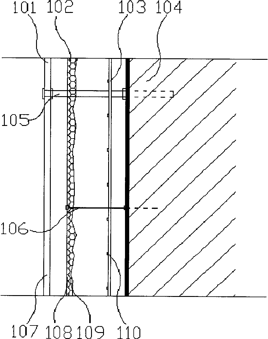
[0029] Such as figure 2 As shown, the construction system of this embodiment is composed of a homogeneous LED base layer 101, a plastic film optical medium layer 102 and a frosted glass image bearing layer 103: the homogeneous LED base layer 101 is composed of LED light-emitting lattices 110 with a pitch of 60mm×60mm Composition, the power of the LED light-emitting dot matrix 110 is 70W / m2, the refresh frequency is ≥1000Hz, and the light-emitting angle of the LED (horizontal viewing angle and vertical viewing angle) is both ≥90 degrees, and then the brightness and color change of the LED light-emitting dot matrix are controlled by the LED controller The plastic film optical medium layer 102 is laid together by a white translucent plastic film and a black plastic film 109, and the black and white texture can be determined according to the artistic effect expressed, and its area should be consistent with the coverage area of ​​the LED base layer; frosted glass The image bearing...

Embodiment 2

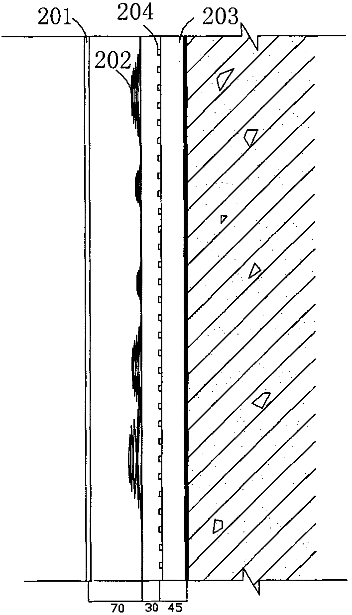
[0032] Such as image 3 As shown, the homogeneous LED base layer 204 of this embodiment is composed of LED light-emitting lattices with a pitch of 40mm×40mm. Vertical viewing angle) ≥ 120 degrees; then the brightness and color change of the LED light-emitting dot matrix are controlled by the LED controller. The optical medium layer 202 is pressed with a tinplate engraving die, and the optical medium layer is 3 cm away from the LED base layer and 7 cm away from the surface image bearing layer. The tinplate itself is opaque. After engraving, the center of the pattern protrudes 0-2cm to form a gap. The light is emitted from the back through the gap, and is refracted and reflected between the optical medium layer 202 and the image bearing layer 201 for many times, and finally on the frosted glass. It has a rose-like pattern on it. Ripple-like patterns vary in size and density in the plane arrangement, controlling the basic layout of the surface image. The radius of the large ci...

Embodiment 3

[0034] Such as Figure 4 As shown, the media interface construction system of this embodiment is composed of a homogeneous LED base layer 303, a tin foil optical medium layer 302, and a translucent frosted glass image bearing layer 301: the homogeneous LED base layer 303 is made of LEDs with a spacing of 20mm×20mm. Composed of dot matrix 304, the power of LED light-emitting dot matrix 304 is 600W / m2, the refresh frequency is ≥1920Hz, and the light emitting angle of LED (horizontal viewing angle and vertical viewing angle) is both ≥120 degrees, and then the brightness of LED light-emitting dot matrix is ​​controlled by the LED controller , color change; the tinfoil optical medium layer 302 is to wrap the 2cm wide hard paper tape with tinfoil, and surround it into several irregularly shaped figures, and connect them as a whole with staples to form a pattern unit, each The area of ​​each irregular figure is controlled at 0.01m2-0.04m2; the frosted glass image bearing layer 301 is...


PUM


Abstract

The invention relates to a media interface construction system based on an LED (Light Emitting Diode) and an optical media, comprising an LED base, an optical media layer and an image bearing layer, wherein the LED base comprises an LED luminous dot matrix and an LED base controller; the LED base is fixed on a carrier; the optical media layer is fixed outside the LED base; the image bearing layer is fixed outside the optical media layer; the LED base is parallel to the optical media layer and a gap exists therebetween; the optical media layer is parallel to the image bearing layer and a gap exists therebetween; and the LED base controller controls the LED luminous dot matrix to send out changeable irradiation light which permeates the optical media layer and finally projects to the image bearing layer so as to generate a dynamic image media interface on the image bearing layer. Compared with the prior art, the media interface construction system based on the LED and the optical media has the advantages of being diversified in construction manner, wide in application range, convenient for maintenance and replacement, low in production cost, simple in manufacturing process and the like.

Description

technical field [0001] The invention relates to a media interface construction system, in particular to a media interface construction system based on LEDs and optical media. Background technique [0002] LED display is a high-tech product that developed rapidly in the world in the late 1980s. With the development and progress of technology, LED display, as an important means of print media communication, can display text, graphics, video and other information, and has gradually become an important part of cities, landscapes and indoor spaces. [0003] At present, the characteristics of LED display screens mainly include full color, high reliability, high brightness, splicing, long service life, strong environmental adaptability, low power consumption, impact resistance, and stable performance. According to the display clarity, LED display can be divided into low pixel and high pixel. In practical applications, low-pixel LED display screens often display single content and...

Claims


Application Information

Patent Timeline
IPC IPC(8): G09F9/33G09G3/32G02B1/10
Inventor 郝洛西
Owner TONGJI UNIV
Why Eureka
Try Eureka