

Automatic discharging device for punching machine
A technology of automatic unloading device and punching machine, which is applied in the direction of stripping device, metal processing equipment, manufacturing tools, etc., which can solve the problems of uneven punching level, increasing the floor area of the factory building, and occupying independent space, etc.
- Summary
- Abstract
- Description
- Claims
- Application Information
AI Technical Summary
Problems solved by technology
Method used
Image

Examples
Embodiment Construction
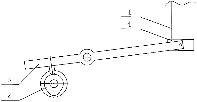
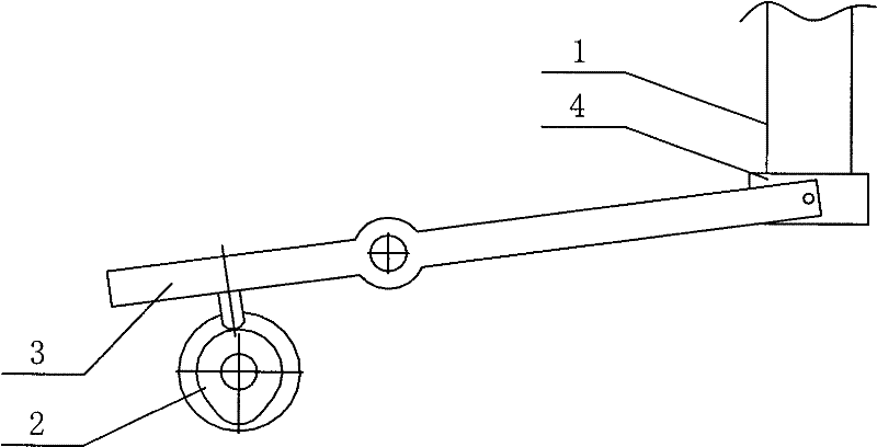
[0011] Such as figure 1 As shown, the punch press automatic unloading device of the present invention is applied to the punch head 1 of the punch press, including a cam 2 and a rocker 3 driven by the cam 2, and a guide and discharge seat 4 is installed at the end of the rocker 3, The material guide and discharge seat 4 is sleeved on the punch 1, and moves with the punch 1, the linear speed of the guide and discharge seat 4 brought by the swing of the rocker 3 is smaller than the punching speed of the punch 1. Post-recovery speed.
[0012] Since the speed of the punch after stamping and recovery is greater than the lifting speed of the guide and unloading seat, a relative displacement occurs between the punch and the guide and unloading seat, so that the blank that is tightly set on the punch after stamping can be It automatically falls back to the position of the mold due to the resistance of the material guide and discharge seat, which can ensure the smooth progress of each ...
PUM
 Abstract
Description
Claims
Application Information