Selective laser sintering scanning method

A technology of laser sintering and scanning method, which is applied in the field of laser scanning, which can solve the problems of very high matching between scanning speed and laser power, reducing the accuracy of parts, and uneven laser intensity, so as to achieve uniform laser scanning intensity and ensure product quality , The effect of consistent scanning speed

Active Publication Date: 2011-09-07
HUNAN FARSOON HIGH TECH CO LTD
View PDF6 Cites 10 Cited by
  • Summary
  • Abstract
  • Description
  • Claims
  • Application Information

AI Technical Summary

Problems solved by technology

There are two commonly used corner point scanning processing methods: one is to start deceleration near the corner and reduce the laser power at the same time. Gradually increase the laser power and scan the laser along the direction behind the corner. This method is easy to control, but it requires very high matching between the scanning speed and the laser power, which will easily lead t

Method used


Image

  • Selective laser sintering scanning method
  • Selective laser sintering scanning method
  • Selective laser sintering scanning method

Examples


Embodiment

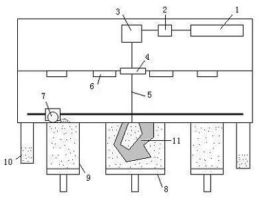
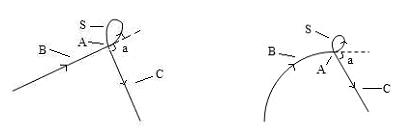
[0011] The equipment that the inventive method adopts is as figure 1 As shown, in the SLS equipment, the powder feeding device 9 sends a certain amount of powder to the worktable, and after the powder is preheated, the powder spreading roller 7 evenly spreads the powder on the upper surface of the molded part 11 in the working cylinder 8 , the excess powder is recovered to the overflow powder cylinder 10, the heating device 6 heats the laid powder to a temperature just below the sintering point of the powder, the laser beam 5 emitted from the laser 1 is reflected by the prism 2 to the vibrating mirror system 3, and vibrates The mirror system 3 controls the laser beam 5 to pass through the laser window 4 to the working table for filling and scanning sintering of the cross-section powder of the workpiece 11 . Such as figure 2 As shown in -4, a is the sharp corner of the laser scanning. The laser scans to the vertex A at a constant speed along the side B with the speed v and po...


PUM


Abstract

The invention discloses a selective laser sintering scanning method. When a sharp corner is met in a selective laser sintering process, a sealed curved-form empty jump is adopted to change the scanning direction, and the scanning speeds at the front and back of the corner are guaranteed to be consistent, thus uniform laser scanning intensity and scanning accuracy of the sharp corner are guaranteed.

Description

technical field [0001] The invention relates to a laser scanning method used in the selective laser sintering process, in particular to a laser scanning method for sharp corners in the selective laser sintering process. Background technique [0002] Rapid Prototyping (RP) is an advanced manufacturing technology with distinctive features such as digital manufacturing, high flexibility and adaptability, direct CAD model drive, fast speed, and rich and diverse material types. Since the late 1980s, So far, it has become a pillar technology in modern advanced manufacturing technology. Selective Laser Sintering (SLS) is one of the fastest-growing rapid prototyping technologies in recent years. It uses powder materials as raw materials and uses laser to scan the cross-section of a three-dimensional entity layer by layer to complete prototype manufacturing. The complexity of the shape is limited, no tooling and molds are required, and the application range is wide. The basic proce...

Claims


Application Information

Patent Timeline
IPC IPC(8): B22F3/105
CPCY02P10/25
Inventor 许小曙
Owner HUNAN FARSOON HIGH TECH CO LTD
Why Eureka
Try Eureka