
Mold cutting tool and manufacture method thereof

A die-cutting knife and cutter body technology, applied in metal processing and other directions, can solve the problems of high production cost and use cost, complicated die-cutting knife processing, and inability to be widely used, so as to prolong the service life, strengthen the strength, and increase the stability. Effect

Inactive Publication Date: 2011-09-07
天津普瑞特产品标识有限公司
View PDF5 Cites 10 Cited by
  • Summary
  • Abstract
  • Description
  • Claims
  • Application Information

AI Technical Summary

Problems solved by technology

The die-cutting accuracy of the engraving knife and etching knife can reach ±0.1mm, but because the processing of the die-cutting knife itself is relatively complicated, its production cost and use cost are high, and it cannot be widely used

Method used


Image

  • Mold cutting tool and manufacture method thereof
  • Mold cutting tool and manufacture method thereof

Examples


Embodiment Construction

[0024] The present invention will be described in detail below with reference to the drawings and examples.

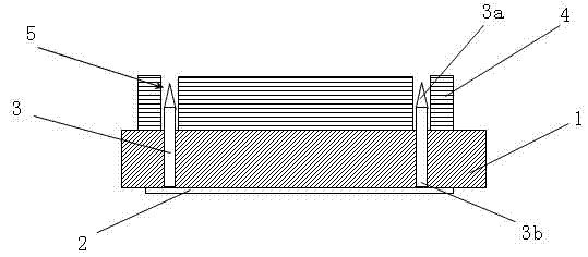
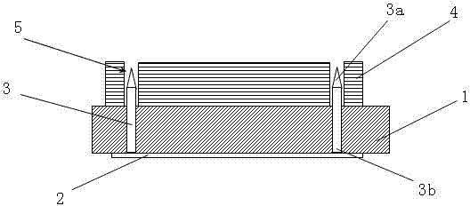
[0025] like figure 1 Shown, die-cutting knife of the present invention comprises: base plate 1, constitutes the main base material of die-cutting knife, supports the knife body of fixed die-cutting knife, and the size of base plate is selected according to the size of die-cutting pattern; Fixed on the bottom plate, the knife body is composed of multiple sections, the blade 3a of the knife body protrudes outward from the front of the bottom plate, and is used as the cutting part in the die-cutting action. The metal with less deformation can be used as the bottom plate, iron plate, copper plate or steel plate can meet the needs very well, and the corresponding selection can be made according to the specific difference in the required strength. Splicing forms the corresponding die-cutting pattern, selects multiple corresponding cutter bodies 3 according to the number of ...


PUM


Abstract

The invention discloses a mold cutting tool comprising a bottom plate and a cutting tool body, wherein the bottom plate is made of a metal material and is provided with a cutting tool containing gap, and the cutting tool ridge of the cutting tool body is fixed in the cutting tool containing gap. In the manufacture method of the mold cutting tool, the bottom plate made of the metal material is adopted, the cutting tool containing gap is machined on the bottom plate so as to intensify the strength of the bottom plate, and the cutting tool body and the bottom plate can be more stably and tightly combined. When the mold cutting tool is stressed when being used, the cutting tool containing gap has small possibility of widening because of deformation, thereby increasing the stability of the cutting tool body under the working state, improving the mold cutting precision of the mold cutting tool so as to prolong the service life of the mold cutting tool, reducing links of filling up the cutting tool, supplementing the cutting tool, changing the cutting tool and the like in the operation process, and improving working efficiency. Meanwhile, because the mold cutting tool is combined by machining by steps, machining cost and machining complexity are far lower than those of the integral machining of a graver or a etching knife, and thus production cost is lowered while mold cutting precision is guaranteed in the use process.

Description

technical field [0001] The invention relates to the technical field of die cutting knives, in particular to a die cutting knife which adopts a base plate made of metal and installs a knife body through a knife slit on the base plate to improve die cutting precision and a manufacturing method thereof. Background technique [0002] Die-cutter has both the functions of mold and knife. It can cut off or press out the folding marks of the product. It has a wide range of applications and can be used for printed matter, plastic sheet, insulation board of electronic products, leather and other thin sheets and sheet materials. [0003] In the printing and packaging industry, die-cutting is a necessary subsequent process. The method of use is to clamp the die-cutting knife in the die-cutting plate frame of the die-cutting machine, and transport the product to the die-cutting platform through the operation of the die-cutting machine. The cutting die is subjected to pressure from the eq...

Claims


Application Information

Patent Timeline
Patent Type & Authority Applications(China)
IPC IPC(8): B26F1/44
Inventor 余峰伟
Owner 天津普瑞特产品标识有限公司
Learn More