
Film sticking method and equipment

A film sticking equipment and film sticking technology, applied in the fields of electrical components, packaging, semiconductor/solid-state device manufacturing, etc., can solve problems such as the inability to clamp the film 103 smoothly, direct stretching or shrinking of the wafer, waste in the width direction, etc., to achieve deformation Small size, save film, improve film quality

Inactive Publication Date: 2011-09-07
上海技美科技股份有限公司
View PDF5 Cites 14 Cited by
  • Summary
  • Abstract
  • Description
  • Claims
  • Application Information

AI Technical Summary

Problems solved by technology

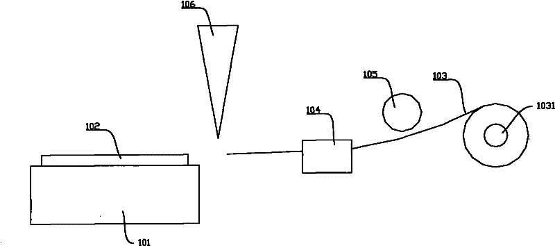
In this way, when sticking the film, the pulled out adhesive film 103 just needs to cover the edge of the wafer along the length direction, and there is no waste of the adhesive film along the length direction, but the waste is relatively large along the width direction.
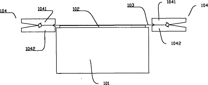
The second situation is that if the width of the adhesive film 103 is smaller than the width of the base 101, then even if the clip 104 is opened, since the adhesive film 103 has been pasted on the wafer 102, the clip 104 returns to the position process before starting to stick the film. , or it will be blocked by the adhesive film attached to the wafer 102; or the two side edges in the width direction of the adhesive film 103 will be separated from the clip 104, even if the clip 104 returns to the position before the film is attached, it cannot be clamped smoothly. Film 103, will affect the next film application
Since the adhesive film has been adhered to the wafer at this time, and the wafer cannot be directly stretched or shrunk in the radial direction, the stress generated by the stretching of the adhesive film will cause the wafer to bend

Method used


Image

  • Film sticking method and equipment
  • Film sticking method and equipment
  • Film sticking method and equipment

Examples


Embodiment Construction

[0046] The present invention will be described in detail below in conjunction with the drawings:

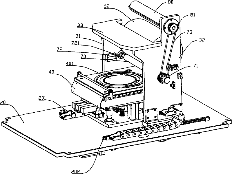
[0047] Such as image 3 , Figure 4 , Figure 5 As shown, the film sticking device includes a base plate 20. Two parallel guide rails (201, 202) are provided on the upper surface of the base plate 20.

[0048] The bracket plate 31 and the bracket plate 32 are arranged on the base plate 20 in parallel. Two sliding blocks 311 are installed at the bottom of the support plate 31. The two sliding blocks 311 are respectively provided with grooves (not shown in the figure) to cooperate with the guide rail 201, so that the support plate 31 can only move along the guide rail 201 when it moves. The mounting method of the support plate 32 is the same as that of the support plate 31. The upper ends of the support plate 31 and the support plate 32 are both connected with the cover plate 33. The bracket plate 31, the bracket plate 32 and the cover plate 33 form a movable gantry.

[0049] A guide...


PUM


Abstract

The invention discloses a film sticking method which is characterized in that an adhesive film roll is driven by an idler wheel for rolling an adhesive film to rotate. By using the film sticking method disclosed by the invention, the adhesive film only needs to overcome the viscous force among the layers of the adhesive film without the need of overcoming the rotating resistance of a roller in the film sticking process, and the viscous force is extremely small, thus compared with the tradition method, through the film sticking method and the film sticking equipment disclosed by the invention,the tensile force to the adhesive film is greatly reduced, the deformation of the adhesive film in the length direction is extremely small, and the tensile force after sticking is also extremely small.

Description

Technical field [0001] The invention relates to a film sticking method and film sticking equipment. In particular, it relates to a film attaching method and film attaching equipment used in the field of semiconductor production. Background technique [0002] After wafer production is completed, packaging testing is required. Wafer production and packaging testing are often carried out in different factories, so transportation and transfer between different locations is required. For the sake of wafer safety when moving, the thickness of wafers manufactured by the fab is usually above 700um to prevent cracking during the transfer process. And as the wafer size increases, its thickness is gradually increasing. [0003] In the use of wafers, the development trend of chips is getting thinner and thinner. Therefore, it is necessary to thin the wafer before packaging and testing. Usually the circuit side of the wafer, that is, the side that completes the chip function, is called the...

Claims


Application Information

Patent Timeline
Patent Type & Authority Applications(China)
IPC IPC(8): B65B33/02H01L21/00
Inventor 张明星
Owner 上海技美科技股份有限公司
Learn More