Pressure stabilizing device and pressure stabilizing method for pneumatic equipment

A technology of voltage stabilizer and equipment, applied in mechanical equipment, gas/liquid distribution and storage, pipeline system, etc., can solve the problems of increasing labor intensity of employees, increasing investment, insufficient gas supply pressure, etc., to avoid product quality and output The effect of lowering, reducing labor intensity and improving yield rate

Inactive Publication Date: 2011-09-07
INNER MONGOLIA YILI INDUSTRIAL GROUP CO LTD
View PDF3 Cites 3 Cited by
  • Summary
  • Abstract
  • Description
  • Claims
  • Application Information

AI Technical Summary

Problems solved by technology

[0002] During the production process of the long cylinder line of frozen drinks, when the pneumatic trolleys and other pneumatic equipment on the production line are running, sometimes the air supply pressure is insufficient or unstable in a short period of time, resulting in the inability of the pneumatic trolleys to operate normally and smoothly
For example: the injection force of the injection trolley is not enough, and the material liquid cannot be poured quantitatively, resulting in ultra-light products or a large amount of waste materials; the force of the chopstick ejector under the chopsticks insertion trolley is insufficient, resulting in the chopsticks not being inserted in place and reserved too long, resulting in jamming. At this time, the chopsticks can only be inserted manually, which not only increases the labor intensity of the employees, but also causes many unqualified finished products; the suction power of the slurry suction workstation is not enough, and the material liquid cannot be completely sucked out, and the effect cannot be achieved, etc. Insufficient air pressure will cause damage, which will seriously affect the quality of products and the release of production line capacity, affecting production and increasing investment

Method used


Image

  • Pressure stabilizing device and pressure stabilizing method for pneumatic equipment
  • Pressure stabilizing device and pressure stabilizing method for pneumatic equipment
  • Pressure stabilizing device and pressure stabilizing method for pneumatic equipment

Examples


Embodiment Construction

[0021] The technical solutions provided by the present invention will be further described below in conjunction with the examples.

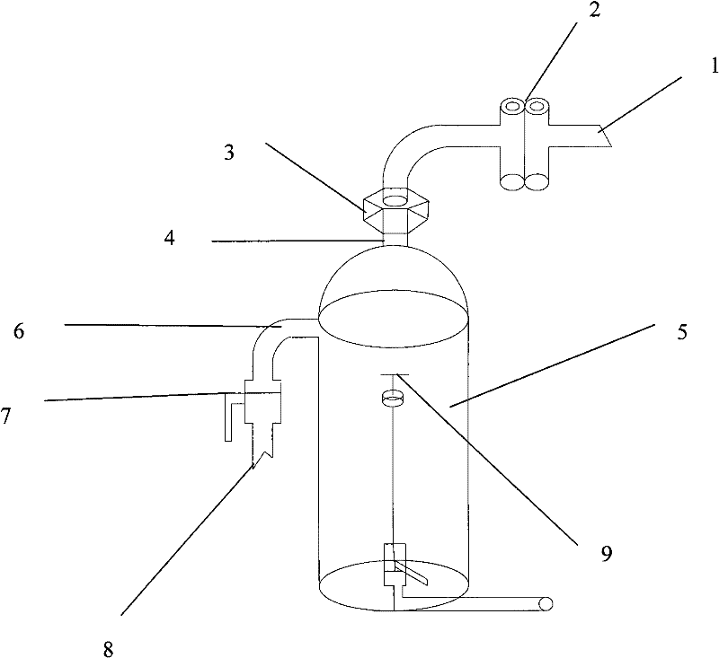
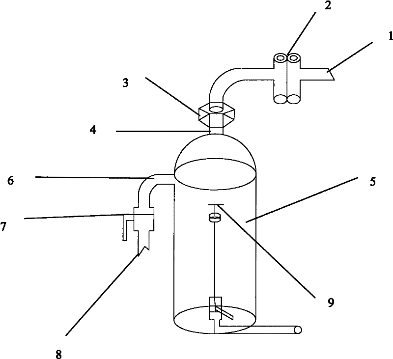
[0022] Such as figure 1 As shown, the compressed air storage tank 5 in the device of the present invention is connected to the compressed air filter 2 through the compressed air intake pipe 1, and then connected to the compressed air supply pipeline 8, installed at the pneumatic equipment of the production line, and stored in the compressed air An air intake interface 4 is provided between the tank 5 and the compressed air filter 2 for connecting the mimeograph 3 and the compressed air intake pipe 1 . After the compressed air enters the air storage tank 5 through the compressed air inlet pipe 1, the air outlet port 6 communicates with the compressed air pipeline through the air supply valve 7, and the air supply valve is in the normally open state during the production stage. A section of pipeline for dredging compressed air (that is, the channe...


PUM


Abstract

The invention relates to a pressure stabilizing device and a pressure stabilizing method for pneumatic equipment. According to the pressure stabilizing device, a compressed air storage tank (5) is arranged on a compressed air supply pipeline of the pneumatic equipment; and the volume of the compressed air storage tank (5) is 60 to 120 liters, and the pressure of the compressed air storage tank (5) is as same as the pressure required by production. By using the device and the method, air pressure is effectively supplied to the pneumatic equipment, influence of the pneumatic equipment such as an injection trolley, a chopstick inserting trolley and the like on the quality and the yield of a product when the air pressure is insufficient or instable is prevented, damage to the pneumatic equipment when the air pressure is instable is avoided, and the labor intensity of staffs is reduced at the same time of reducing the maintenance expense and effectively ensuring safe and stable operation of the equipment.

Description

technical field [0001] The invention relates to the field of voltage stabilization for long cylinder line production, in particular, the invention relates to a voltage stabilizing device and a voltage stabilizing method for pneumatic equipment. Background technique [0002] During the production process of the long cylinder line of frozen drinks, when the pneumatic trolleys and other pneumatic equipment on the production line are running, sometimes the air supply pressure is insufficient or unstable in a short period of time, resulting in the abnormal and stable operation of the pneumatic trolleys. For example: the injection force of the injection trolley is not enough, and the material liquid cannot be poured quantitatively, resulting in ultra-light products or a large amount of waste materials; the force of the chopstick ejector under the chopsticks insertion trolley is insufficient, resulting in the chopsticks not being inserted in place and reserved too long, resulting in...

Claims


Application Information

Patent Timeline
Patent Type & Authority Applications(China)
IPC IPC(8): F17D3/01
Inventor 张燕龙梁林在李国俊
Owner INNER MONGOLIA YILI INDUSTRIAL GROUP CO LTD
Why Eureka
Try Eureka