Diluting device used for on-line water quality analysis

A dilution device, a technology for water quality analysis, applied in the preparation of test samples, etc., can solve the problems of low calculation accuracy of dilution ratio, inability to achieve large dilution ratio, large device volume, etc., and achieve low cost, small volume and high precision. Effect

Active Publication Date: 2012-08-29
HANGZHOU CHUNLAI TECH
View PDF6 Cites 0 Cited by
  • Summary
  • Abstract
  • Description
  • Claims
  • Application Information

AI Technical Summary

Problems solved by technology

However, the existing dilution technology has the problem of being unable to achieve a large dilution ratio, and there are also disadvantages such as large device volume, high cost, and low calculation accuracy of the dilution ratio.

Method used


Image

  • Diluting device used for on-line water quality analysis
  • Diluting device used for on-line water quality analysis
  • Diluting device used for on-line water quality analysis

Examples


Embodiment 1

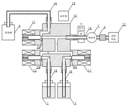
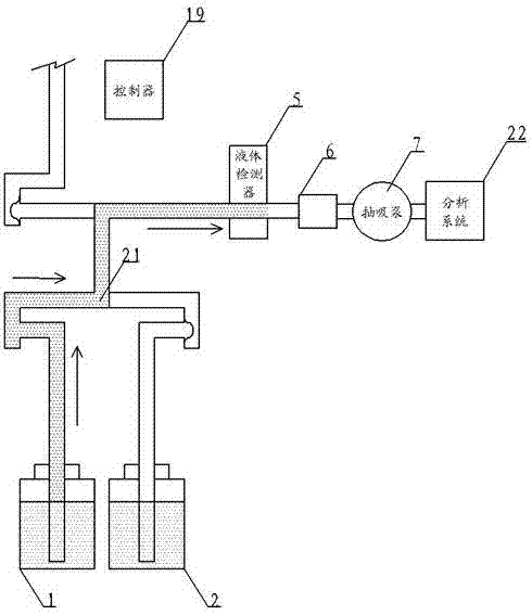
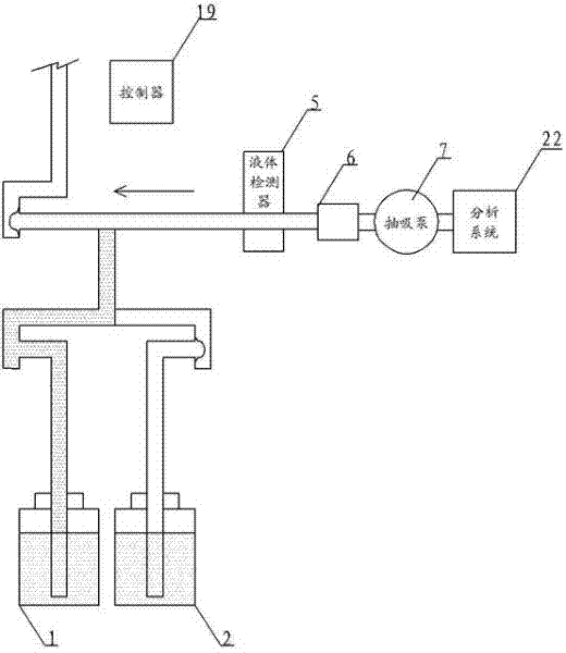
[0017] Such as figure 1 As shown, the dilution device of the present invention includes a water sample box 1, a zero sample box 2, a micrometer tube 3, a waste liquid tank 4, a liquid tester 5, a metering tank 6, and a suction pump 7, and the water sample box is used to store the The sample solution, the zero sample box is used to store the diluent, the micrometer tube 3 is a micrometer pipe, the upper end is connected to the first channel 9, and the lower end is connected to the second channel 10, and one end of the first channel 9 is provided with a first valve 11, and The inflow port of a valve 11 is connected to the first passage 9, and the outflow product is connected to the waste liquid tank 4. The other end of the first passage 9 is provided with a liquid tester 5, a metering tank 6, a suction pump 7 in sequence, and the second passage 10 One end is provided with a second valve 12, and the other end is provided with a third valve 13. The inflow port of the second valve ...

Embodiment 2

[0028] Such as figure 2 As shown, the further preferred solution of the present invention is also provided with a base 14, and the micrometer tube 3, the first channel 9, the second channel 10, the third channel 15, the fourth channel 16, the first channel 10 are integrally arranged through the base 14 Five channels 17, the inlet and outlet of the first valve 11, the second valve 12, and the third valve 13 are connected with the first channel 9, the second channel 10, the third channel 15, the fourth channel 16, and the fifth channel. The ports on one side of 17 are correspondingly connected, and the waste liquid tank 4, the water sample tank 1, the zero sample tank 2, and the liquid tester 5, the metering tank 6, and the suction pump 7 arranged in sequence are connected to the third channel 15, the The ports on the other side of the four channels 16 and the fifth channel 17 are correspondingly connected.

[0029] The work of this embodiment is the same as that of Embodiment...


PUM


Abstract

The invention discloses a diluting device used for on-line water quality analysis, aiming at providing a diluting device used for on-line water quality analysis, wherein the diluting device has the characteristics of high dilution ratio, low cost, small volume and high precision. The technical scheme adopted by the invention is as follows: the diluting device comprises a water sample tank and a zero sample tank, wherein the diluting device is further provided with a micro-metering tube, an effluent tank, a liquid tester, a metering pool and a suction pump; the upper end of the micro-metering tube is connected to a first channel while the lower end of the micro-metering tube is connected to a second channel; one end of the first channel is provided with a first valve; the first channel is connected to the effluent tank through the first valve; the other end of the first channel is connected to the liquid tester, the metering pool and the suction pump in sequence; one end of a second channel is provided with a second valve while the other end of the second channel is provided with a third valve; and the second channel is connected to the water sample tank and the zero sample tank through the second valve and the third valve. The diluting device has the beneficial effects of high dilution ratio, low cost, small volume and high precision.

Description

technical field [0001] The invention relates to a dilution device, in particular to a dilution device for online water quality analysis. Background technique [0002] At present, online water quality analysis instruments have been widely used in the analysis of components in pollution source emissions, and the components analyzed include chemical oxygen demand (COD), ammonia nitrogen, total phosphorus, total nitrogen, heavy metals, etc. Usually, due to the fluctuation of water treatment effect, the concentration of these components will change greatly. In order to adapt to this change, it is necessary for the online water quality analysis instrument to have multiple ranges, and the ranges have a large range ratio. Among them, dilution is a very good means to achieve a large turndown ratio. Generally, the greater the dilution ratio, the greater the turndown ratio can be achieved. However, the existing dilution technology has the problem of being unable to achieve a large di...

Claims


Application Information

Patent Timeline
Patent Type & Authority Patents(China)
IPC IPC(8): G01N1/38
Inventor 于志伟施林辉唐怀武周磊
Owner HANGZHOU CHUNLAI TECH
Why Eureka
Try Eureka