Rapid conductor locking structure

A locking structure and fast technology, applied in the direction of clamping/spring connection, coupling device, contact part, etc., can solve the problems of changing the structure size of metal terminals, prone to false welding, small use range, etc., to achieve great flexibility and extensiveness, improve current carrying capacity, and increase the effect of wire contact area

Inactive Publication Date: 2011-09-07
SHANGHAI AEROSPACE SCI & IND ELECTRIC APPLIANCE RES INST
View PDF3 Cites 8 Cited by
  • Summary
  • Abstract
  • Description
  • Claims
  • Application Information

AI Technical Summary

Problems solved by technology

[0002] At present, the commonly used terminal and wire connections mainly include several termination methods such as welding, crimping, wrapping and IDC (Insulator Displacement Connection). The welding method is widely used due to its low cost and convenient use. Welding has certain requirements for operational skills, and false welding is prone to occur in production; the crimping method is easy to operate and reliable in connection, but the cost is relatively high, and special crimping tools are required to carry out, and this method is also more common; wrapping The method is to wind the wire around the end of the metal terminal, which is inconvenient to operate and has a small range of use; the insulator displacement (IDC) connection method is widely used in electronic products, and it is easy to operate, and a good airtightness can be formed between the terminal and the wire Sexual contact, but this kind of connection is generally not used in large current transmission
Considering the convenience of operation, wire type and specification, assembly cost and scope of use, these termination methods have different degrees of disadvantages. For example, for different types of wires, the structure and size of metal terminals will change, and special Tooling for connecting wires to metal terminals
With the development of technology, the squirrel-cage reed locking wire structure has been widely used due to its reliability and convenience. However, when the wire is thick and works for a long time, there will be hidden dangers such as wire loosening.

Method used


Image

  • Rapid conductor locking structure
  • Rapid conductor locking structure
  • Rapid conductor locking structure

Examples


Embodiment Construction

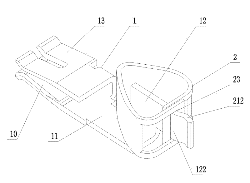
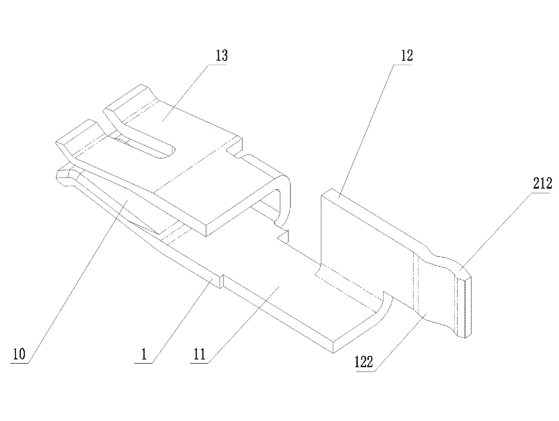
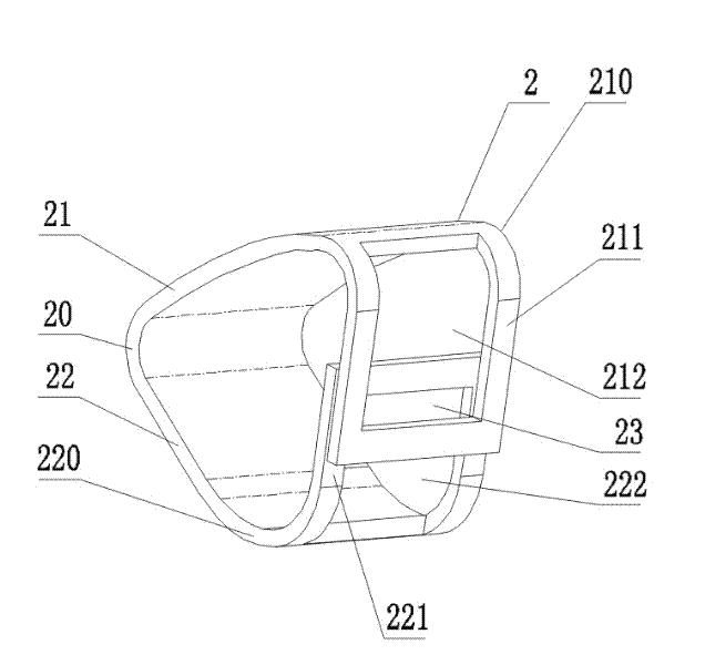
[0011] See attached figure 1 , the present invention includes a metal terminal 1 and a locking coil 2, the metal terminal 1 is formed by connecting the front and rear ends of a lead plate 11 to a butt joint 10 and a crimping plate 12, and the butt joint 10 is two contact pieces 13 connected in parallel; The plate 12 is a pressing plate provided with a front convex hull 121 and a rear convex hull 122, and the pressing plate 12 is connected at right angles to the lead plate 11; The circlip connected by a triangle, the upper cantilever beam 21 is provided with a downwardly bent A lockline window 212, and the lower cantilever beam 22 is provided with an upwardly bent B lockline window 222, and the A lockline window 212 and the B lockline The thread window 222 overlaps to form a slit-shaped thread-locking opening 23, the thread-pressing plate 12 is sleeved with the thread-locking coil 2, and the rear convex hull 122 protrudes from the thread-locking port 23, and the thread-pressing...


PUM


Abstract

The invention discloses a rapid conductor locking structure comprising a metal terminal and a locking spring coil. The rapid lead locking structure is characterized in that the metal terminal is formed by connecting the front end and the rear end of a conductor plate with a butt joint and a tension disc, and the butt joint is formed by two contact plates connected in parallel; the tension disc isa pressing plate provided with a front convex hull and a rear convex hull, the locking spring coil is a snap spring of which an circular arc, an upper cantilever beam and a lower cantilever beam are connected in an equilateral triangle, the tension disc is sheathed with the locking spring coil, and the pressing plate is used for rapidly locking a conductor by the front convex part, the rear convex part and a conductor locking port. Compared with the prior art, the invention has the advantages of simple structure, capability of carrying out connection or disassembly and replacement on different specifications of conductors as required, no needs of special frocks, convenience for operation, enlarged conductor contact area, enhanced electricity bearing capability, rapidness and reliability of conductor connection, flexibility and wide application in the aspect of usage.

Description

technical field [0001] The invention relates to the technical field of electrical connectors, in particular to a wire fast locking structure for connecting wires of different types to metal terminals. Background technique [0002] At present, the commonly used terminal and wire connections mainly include several termination methods such as welding, crimping, wrapping and IDC (insulator displacement connection). Among them, the welding method is widely used due to its low cost and convenient use. Welding has certain requirements for operational skills, and false welding is prone to occur in production; the crimping method is easy to operate and reliable in connection, but the cost is relatively high, and special crimping tools are required, and this method is also more common; wrapping The method is to wind the wire around the end of the metal terminal, which is inconvenient to operate and has a small range of use; the insulator displacement (IDC) connection method is widely ...

Claims


Application Information

Patent Timeline
Patent Type & Authority Applications(China)
IPC IPC(8): H01R13/20H01R27/00H01R4/48
Inventor 曹永泉
Owner SHANGHAI AEROSPACE SCI & IND ELECTRIC APPLIANCE RES INST
Why Eureka
Try Eureka