Method for determining isolation between antennas

A determination method and antenna isolation technology, applied in transmission monitoring, special data processing applications, instruments, etc., can solve problems such as long data acquisition cycle, high possibility of error, and result deviation, so as to save workload, save time, and improve The effect of work efficiency

Inactive Publication Date: 2011-09-07
AEROSPACE DONGFANGHONG SATELLITE
View PDF3 Cites 15 Cited by
  • Summary
  • Abstract
  • Description
  • Claims
  • Application Information

AI Technical Summary

Problems solved by technology

In view of the complexity of the electromagnetic environment, the electromagnetic compatibility test (including the antenna isolation test) has high requirements for the test environment and test equipment, and any error in any link may cause deviations in the results
Therefore, to obtain the antenna isolation through specific tests, the workload is large, the data acquisition period is long, and the possibility of error is large.

Method used


Image

  • Method for determining isolation between antennas
  • Method for determining isolation between antennas
  • Method for determining isolation between antennas

Examples


Embodiment Construction

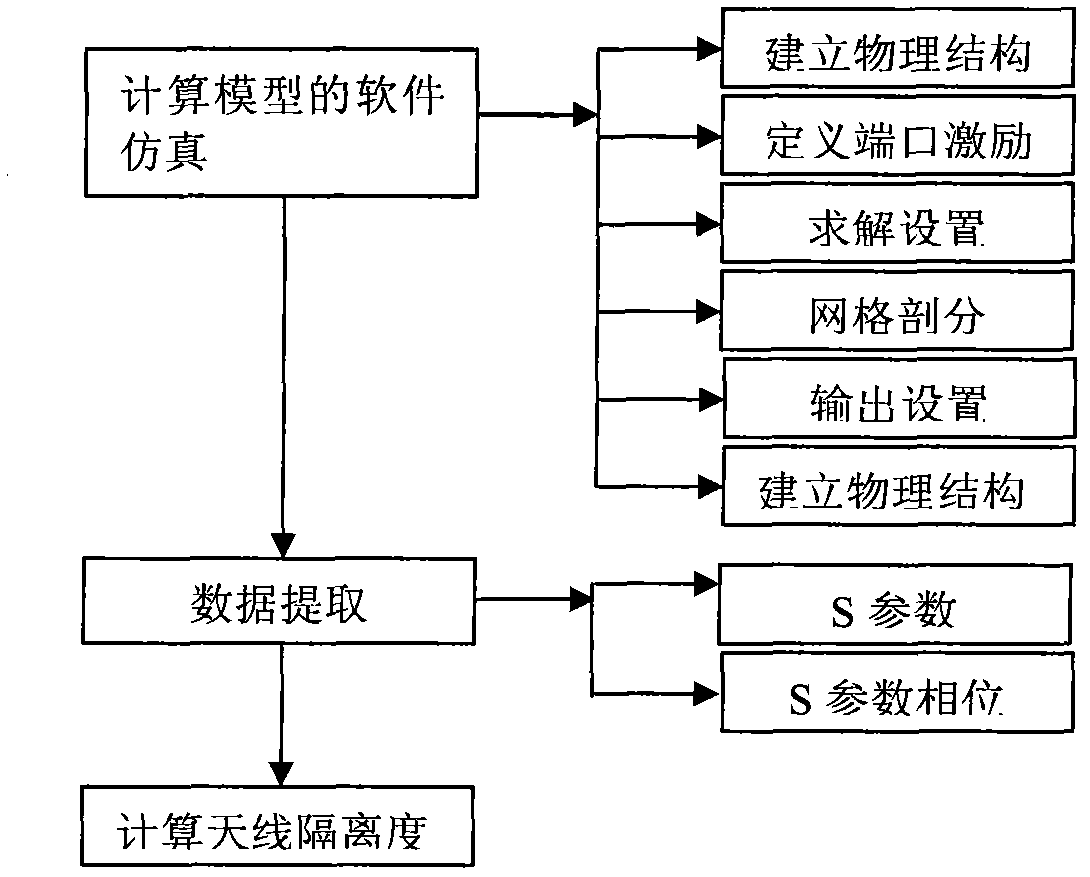
[0015] The method for evaluating the antenna isolation based on the S parameter of the present invention actually obtains data such as the S parameter of the antenna through simulation software, and directly obtains the antenna isolation through formula calculation. The derivation of the formula for calculating the antenna isolation is to equate the antenna system into a microwave network. According to the relationship between the power and voltage of the transceiver antenna port and the S parameter, it is derived from the definition formula of the isolation degree commonly used in engineering, and a correction factor is added. The specific derivation process as follows:

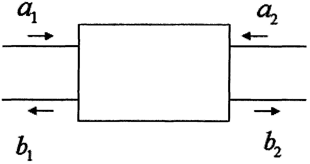
[0016] The S parameter is one of the scattering parameters describing the microwave network, which represents the relationship between the incident wave and the scattered wave at the network port. like figure 1 In the two-port network shown, the port signals are (a 1 , b 1 ) and (a 2 , b 2 ), a 1 and a...


PUM


Abstract

The invention provides a method for determining isolation between antennas, which comprises the following steps of: modeling the antennas of which the isolation needs to be computed; enabling the antennas of which the isolation needs to be computed to be equivalent to a multi-port microwave network, wherein each antenna corresponds to a port; and then, computing the isolation between the antennas by using a formula, wherein C represents the isolation between the antennas, S11 and S21 respectively represent S parameters between two ports, and theta represents the phase position corresponding to S11. The method provided by the invention, which is used for directly computing the isolation between the antennas through the formula, is quick and convenient and avoids the defects that the isolation between antennas is acquired through complicated tests and many interference factors exist in the tests in the past, so that the result is closer to the theoretical condition, and the workload is greatly lowered. The invention provides a definite data index for analyzing electromagnetic energy crosstalk generated after different radio frequency devices pass through antennas.

Description

technical field [0001] The invention relates to a method for analyzing the isolation degree of the same multi-device antenna. Background technique [0002] Antenna isolation is an important index to characterize the antenna coupling characteristics. In engineering, the definition of antenna isolation is usually represented by power and voltage. [0003] In engineering, the formula for expressing the antenna isolation by the power of the transmitting and receiving antenna is: C represents the size of the antenna coupling degree, P r Represents the power received by the receiving antenna, P t Indicates the transmitting power of the transmitting antenna. [0004] In engineering, voltage can also be used to represent antenna isolation, and U 1 , U 2 are the port voltages of the transmitting antenna and the receiving antenna respectively, and the unit is μV. Redefine the transmitting and receiving power of the antenna by voltage and impedance, then the formula can be exp...

Claims


Application Information

Patent Timeline
Patent Type & Authority Applications(China)
IPC IPC(8): H04B17/00G06F19/00
Inventor 高杰宁金枝王淼李红宝杨争光
Owner AEROSPACE DONGFANGHONG SATELLITE
Why Eureka
Try Eureka