Crushing device with two-way rotation

A crushing device with two-way rotation technology, which is applied in grain processing and other directions, and can solve the problems of occupying leak hole space, unfavorable sliding of crushed objects, and easy jamming of crushed objects, etc.

Inactive Publication Date: 2011-09-14
叶德坚
View PDF4 Cites 9 Cited by
  • Summary
  • Abstract
  • Description
  • Claims
  • Application Information

AI Technical Summary

Problems solved by technology

[0002] For example, in the existing small-scale pulping machines using blades or machines for making powder paste, etc., after completing operations such as pulping or powder paste, there will be too much pulverized material that can be crushed. It is a big shortcoming, and the main reason is that there must be a distance between the blade and the machine body to hide the crushed objects. The distance causes the crushed objects to follow the movement of the blade, and it is difficult for the blade to completely crush the crushed objects. It is inevitable to produce remaining crushed objects that can be crushed. of
[0003] As the patent No.: the two-way rotating crushing device of 201010019254. In the leakage hole, according to the rotation direction of the cutter wheel A (the side in the front direction) forms an angle with the side near the cutter wheel A, the angle formed between 90 and 180 degrees can be used to prevent the crushed objects from reversing The function of the storage barrel is easy to jam the pulverized objects. The solid part of the angle will cause the leakage hole to extend in the front leakage hole entering the pulverized object, which will occupy the space of the leak hole, which is not conducive to the pulverized object sliding into the cutter wheel A. in the sipe

Method used


Image

  • Crushing device with two-way rotation
  • Crushing device with two-way rotation
  • Crushing device with two-way rotation

Examples


Embodiment Construction

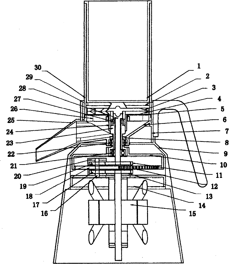
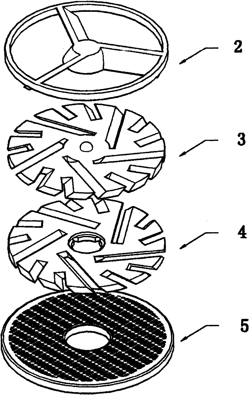
[0014] The following is combined figure 1 and figure 2 To implement this pulverizing device, do a more specific description:

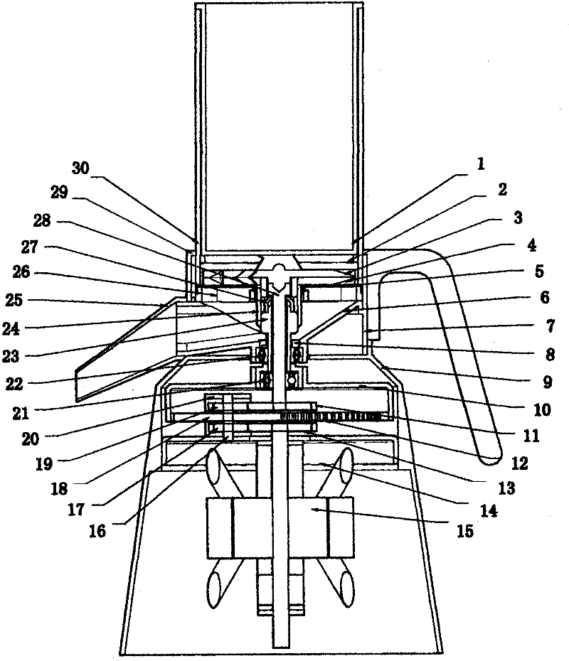
[0015] Such as figure 1 The pulverizer structure provided is a preferred vertical mode for implementing the present invention.

[0016] The present invention can also be applied to horizontal or inverted pulverizers: the motor, the inner gear and five gears, the inner shaft and the outer shaft are the driving parts of the pulverizer, and can be set at the end where the pulverizer enters the pulverized material Or discharge one end of the pulverized material; among them, the fixed material rack, cutter wheel A, cutter wheel B, sieve, sieve seat, funnel, etc. are the parts that the pulverized material needs to pass through, and the installation sequence does not need to be changed; among them, the storage cylinder, The handle and its collar, the discharge port, the base supporting the pulverizer body, the cylindrical body connecting the scattered par...


PUM


Abstract

The invention relates to a material fixing frame. The material fixing frame is characterized in that an included angle is formed by the side surface (the side surface in the leaking hole according to the forward direction of the rotating direction of a cutter wheel A) in a leaking hole and the side surface close to the cutter wheel A, and the included angle can be selected between 0 degree and less than 90 degrees; and the included angle can be more beneficial to leading crushed materials to slide into a cutting groove of the cutting wheel A, preventing uncrushed materials or materials without being crushed completely from moving along the rotation of the cutter wheel A, assisting the crushed materials to enter the cutter groove of the cutter wheel A, playing a role in fixing the crushed materials and leading the cutter wheel A to carry out solid crushing on the crushed materials.

Description

Technical field: [0001] The invention relates to the technical fields of shearing pulverization and attrition pulverization. Background technique: [0002] For example, in the existing small-scale pulping machines using blades or machines for making powder paste, etc., after completing operations such as pulping or powder paste, there will be too much pulverized material that can be crushed. It is a big shortcoming, and the main reason is that there must be a distance between the blade and the machine body to hide the crushed objects. The distance causes the crushed objects to follow the movement of the blade, and it is difficult for the blade to completely crush the crushed objects. It is inevitable to produce remaining crushed objects that can be crushed. of. [0003] Such as the patent No.: 201010019254.X's two-way rotating crushing device, though can change the above-mentioned shortcoming, but wherein the fixed material rack uses the side in its leakage hole (is in the ...

Claims


Application Information

Patent Timeline
Patent Type & Authority Applications(China)
IPC IPC(8): B02C18/06B02C18/16B02C18/18B02C23/12
Inventor 叶德坚
Owner 叶德坚
Why Eureka
Try Eureka