Roller set for universal mill

A universal rolling mill and roll group technology, applied in the direction of rolls, metal rolling stands, metal rolling mill stands, etc., can solve the problem of complex structure of spring slider mechanism, no reliable interlock, limited moving in or moving out speed, etc. problems, to achieve the effect of promoting the use, low manufacturing cost, and reducing the difficulty of roll changing operations

Active Publication Date: 2011-09-14
CISDI ENG CO LTD
View PDF5 Cites 7 Cited by
  • Summary
  • Abstract
  • Description
  • Claims
  • Application Information

AI Technical Summary

Problems solved by technology

[0004] In the prior art, the patent 03156744.4 discloses a roll set for a universal frame, the rolls of the roll set are interlocked by support pins and struts to form a whole, which meets the requirements of moving the roll set into or out of the frame as a whole process requirements, but this technology still has the following deficiencies: a. The vertical roller is only placed on the top of the support rod, the vertical roller can still move in the horizontal direction, and does not form a reliable interlock, when the roller When the group moves out or into the frame, the support rod only relies on the friction with the guide groove on the vertical roller to drive the vertical roller to move out or in, resulting in poor positioning interlocking of the vertical roller, which limits the speed of moving in or out of the roller group , the rolling mill cannot be put into work quickly, and at the same time, when the rolling mill is working, the reciprocating motion of the vertical roller in the horizontal direction will cause the guide groove on the vertical roller and the top of the support rod to wear each other, resulting in further deterioration of its interlocking and serious wear Finally, the problem that the vertical roller cannot be pulled out is even caused; b. The upper horizontal roller is supported by the support pin on the vertical roller, and is unlocked by the movement of the spring slider, and a certain space is formed after the slider is removed, so that the upper horizontal roller The roller can continue to move downward, and the vertical roller can also move freely in the horizontal direction, but its movement in or out also depends on the friction between the support pin and the slider on the upper horizontal roller, and the positioning interlock is also poor, and it is difficult to form Reliable interlocking, and the spring slider mechanism of the upper horizontal roll has a complex structure, inconvenient operation, low reliability and poor maintainability under harsh working conditions, and it is difficult to be effectively used at the rolling site

Method used


Image

  • Roller set for universal mill
  • Roller set for universal mill
  • Roller set for universal mill

Examples


Embodiment 1

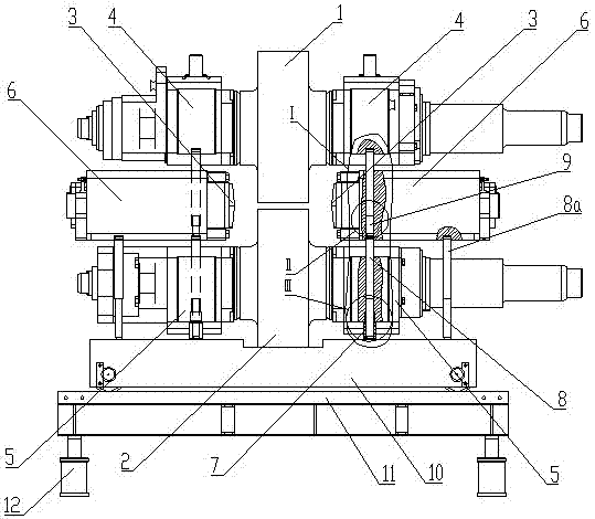
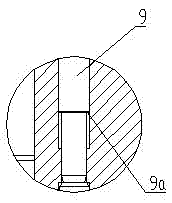
[0040] Such as Figure 1 to Figure 6 As shown, the roll set used in the universal rolling mill in this embodiment includes an upper horizontal roll 1, a lower horizontal roll 2 and a pair of vertical rolls 3 that jointly enclose a rolling passage, and the two ends of the upper horizontal roll 1 are connected to the two sides respectively. The two ends of the lower horizontal roll 2 are rotatably matched with the two lower chocks 5 respectively, and the pair of vertical rolls 3 are respectively rotatably matched with the two vertical roll chocks 6. The roll group can be moved into the universal rolling mill. The roll change operation is carried out in and out of the frame archway. The roll group also includes a quick roll change device. The fast roll change device includes four lower horizontal roll positioning rods 7 distributed on the left and right sides of the rolling channel. Four vertical roll positioning rods 8, four upper horizontal roll positioning rods 9 and a liftabl...

Embodiment 2

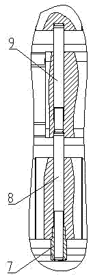
[0050] Such as Figure 7 and Figure 8 As shown, the roll set used in the universal rolling mill of this embodiment is compared with that of Example 1, mainly because of the difference between the roll set of the two-roll structure and the roll set of the four-roll structure, and the roll set includes the upper horizontal roll 1 and the lower horizontal roll 2. The two ends of the upper horizontal roller 1 are rotatably matched with the two upper bearing housings 4 respectively, and the two ends of the lower horizontal roller 2 are respectively rotatably matched with the two lower bearing housings 5. The roll set also includes a quick roll changing device, The quick roll changing device includes four lower horizontal roll positioning rods 7 distributed on the left and right sides of the roll gap, four upper horizontal roll positioning rods 9 and a liftable roll changing trolley 10, each side of the roll gap lower horizontal roll positioning rods and two positioning rods for t...


PUM


Abstract

The invention discloses a roller set for a universal mill, and the roller set comprises an upper horizontal roller, a lower horizontal roller, a pair of upright rollers and a quick roller-exchanging device, wherein the upper horizontal roller is provided with two upper bearing bases; the lower horizontal roller is provided with two lower bearing bases; each upright roller is provided with a roller bearing base; and the quick roller-exchanging device comprises a lower horizontal roller positioning rod, an upright roller positioning rod, an upper horizontal roller positioning rod and a lifting roller-exchanging trolley. When the roller is needed to be exchanged, the roller-exchanging trolley lifts and then drives all the positioning rods to stretch into countersinks which are correspondingly arranged on the bearing bases, thereby realizing the reliable support positioning, integrally forming the roller set, avoiding the relative movement among rollers and abrasion of the positioning rods when the roller set is quickly moved out or loaded, and being reliable in interlocking. When the roller set is needed to work, the roller-exchanging trolley descends so as to release all the supportpositioning relationships and then the roller set can start working quickly. The roller set for the universal mill has a simple and reasonable structure and can be used for efficiently increasing thereliability and maintainability of the roller set, reducing the difficulty of roller-exchanging operation, shortening the roller-exchanging time, and increasing the production efficiency.

Description

technical field [0001] The invention relates to section steel production equipment, in particular to a component of a universal rolling mill. Background technique [0002] At present, the production of section steel generally adopts the universal rolling method, among which the universal rolling mill is the most important equipment for the production of section steel. During the rolling process of the universal rolling mill, the rolls wear out quickly, and the roll group needs to be replaced frequently. Therefore, the roll changing operation The length of time determines the production efficiency of the universal rolling mill to a large extent. [0003] Roll changing process requirements: During the roll changing operation, the bearing housings of the upper and lower horizontal rolls of the roll group and the bearing housings of the left and right vertical rolls need to support and position each other to form a whole, and after the rolls are assembled into the rolling mill, ...

Claims


Application Information

Patent Timeline
Patent Type & Authority Applications(China)
IPC IPC(8): B21B27/00B21B31/08
Inventor 陈义李图学赵远峰闵建军
Owner CISDI ENG CO LTD
Why Eureka
Try Eureka