Supercharge Your Innovation With Domain-Expert AI Agents!

Compensation mechanism for stress deformation of spindle box of machine tool

A stress deformation, machine tool spindle technology, applied in metal processing mechanical parts, metal processing equipment, maintenance and safety accessories, etc., can solve the problems of the stress deformation of the headstock, which cannot be compensated for the position, and the ram shaft is deformed upwards, and achieves weight The effect of light weight, increased span and compact structure

Inactive Publication Date: 2011-09-14
SANY GRP
View PDF5 Cites 5 Cited by
  • Summary
  • Abstract
  • Description
  • Claims
  • Application Information

AI Technical Summary

Benefits of technology

This patented technology describes an improved design for a stressed or distorted portion (headstock) of a machine tool called Spinning Center®. It achieves this by adding extra guides along its length instead of just one single rail across each side. These guiding elements help prevent any bending moment from causing damage during machining operations without compromising their strength. Additionally, there may be multiple levels of damping within certain parts of the Stress Distortion Support System: One level includes three layers of steel plates arranged at different angles around the entire system's middle section. Another layer consists of conductive rubber disc springs placed under tension between these steel plats. Finally, another set of guide rails act like cushions against external forces such as impact loads. Overall, this innovative solution allows for precise and efficient correction of stress and displacement in the Headstock itself.

Problems solved by technology

This patents discuss how adding an external weight can help prevent distortion caused by changes in gravitational forces during operation of the machines' heads. However, current methods have limitations when trying to achieve this purpose.

Method used


Image

  • Compensation mechanism for stress deformation of spindle box of machine tool
  • Compensation mechanism for stress deformation of spindle box of machine tool
  • Compensation mechanism for stress deformation of spindle box of machine tool

Examples


Embodiment Construction

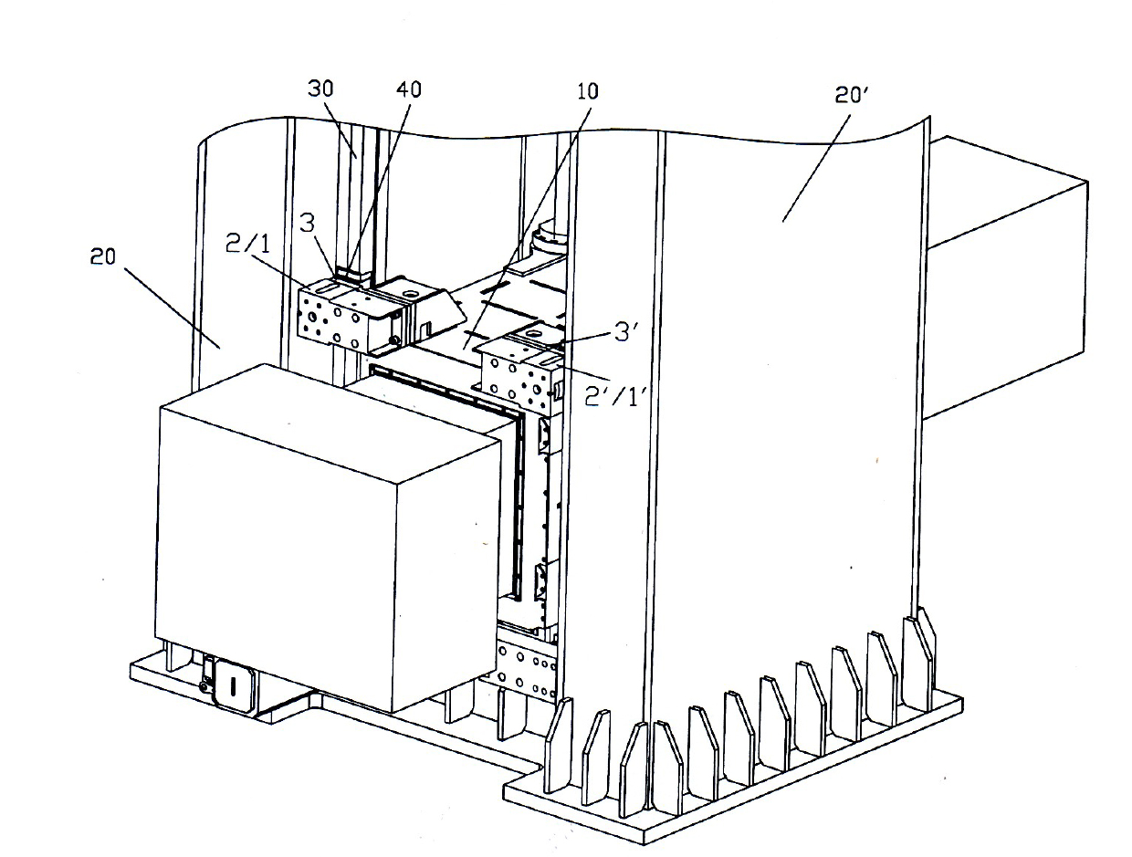
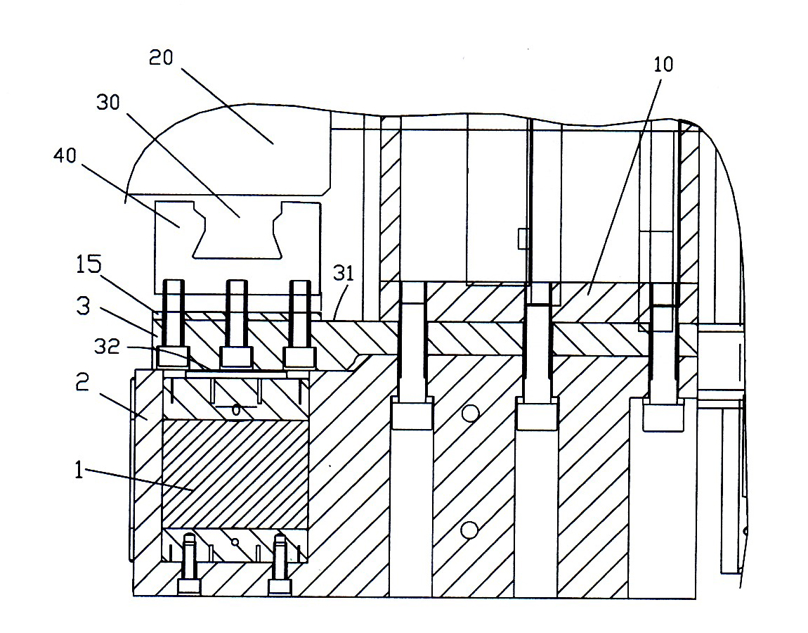
[0028] see Figure 1 ~ Figure 3 , the compensation mechanism for the stress deformation of the spindle box of the machine tool, the spindle box 10 is located between the two columns 20, 20', forming a door-type thermal deformation symmetrical structure, and the front and rear contact surfaces between the spindle box 10 and the two columns 20, 20' are respectively Two guide rails 30 and a slider 40 are provided to form a vertical guide support.

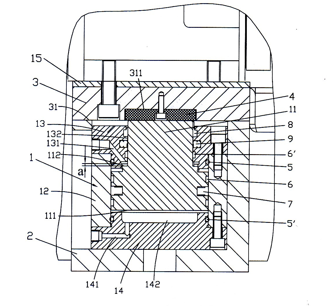
[0029] The compensation mechanism includes two compensation oil cylinders 1, 1', which are respectively arranged in a support shell 2, 2', and the two support shells 2, 2' are symmetrically installed on both sides of the upper end surface of the rear part of the headstock 10 respectively. Two transition connecting plates 3, 3 ', the two ends of a side surface 31 of the transition connecting plate 3 (taking the compensation oil cylinder 1 and the transition connecting plate 3 as an example, the same below) respectively connect the two s...


PUM


Abstract

The invention relates to a compensation mechanism for stress deformation of a spindle box of a machine tool, wherein the spindle box is arranged between two upright columns, thereby forming a gate-type thermal deformation symmetrical structure; two guide rails and sliding blocks are respectively arranged on front and back contact walls between the spindle box and the two upright columns, thereby forming a vertical guiding support; the compensation mechanism further comprises two compensation cylinders, two transition connection plates and two support shells; the two compensation cylinders are respectively arranged in the two support shells; the two support shells are symmetrically arranged at two sides of the upper end face on the rear part of the spindle box; two ends on one side wall of each transition connection plate are respectively connected to two sides of the upper end face on the rear part of the spindle box and corresponding to the sliding blocks of the guide rails; the two support shells, in which the compensation cylinders are arranged, are respectively arranged on the other side walls of the transition connection plates corresponding to the sliding blocks; and the piston rod ends of the compensation cylinders prop against the other side walls of the transition connection plates corresponding to the sliding blocks. According to the compensation mechanism provided by the invention, the deformation compensation mechanism is arranged inside a sliding sleeper. The compensation mechanism provided by the invention can be used for solving the problem of suspension stretching flexible deformation caused by the change of gravity center of a spindle component in the moving process of the spindle box and can be used for dynamically compensating the stress deformation generated by the spindle box in real time.

Description


Claims


Application Information

Patent Timeline
Owner SANY GRP
Features
  • R&D
  • Intellectual Property
  • Life Sciences
  • Materials
  • Tech Scout
  • Unparalleled Data Quality
  • Higher Quality Content
  • 60% Fewer Hallucinations
Learn More