Electric energy meter carrying manipulator suitable for meter box

A technology of electric energy meter and manipulator, applied in the field of electric energy meter transfer equipment, can solve the problems of incompatibility, high labor intensity, low work efficiency, etc.

Inactive Publication Date: 2011-09-14
STATE GRID ZHEJIANG ELECTRIC POWER +1
View PDF6 Cites 44 Cited by
  • Summary
  • Abstract
  • Description
  • Claims
  • Application Information

AI Technical Summary

Problems solved by technology

[0002] For the convenience of the verification of the electric energy meter, the electric energy meter is generally moved from the meter box to the tooling board for verification. After the verification and other procedures are completed, the electric energy meter is moved back from the tooling board to the meter box. At present, the above-mentioned transfer work is mostly manual operation. This working method is labor-intensive and low-efficiency, and is no longer suitable for the production needs of industrial automation. Moreover, because the electric en

Method used


Image

  • Electric energy meter carrying manipulator suitable for meter box
  • Electric energy meter carrying manipulator suitable for meter box
  • Electric energy meter carrying manipulator suitable for meter box

Examples


Embodiment 1

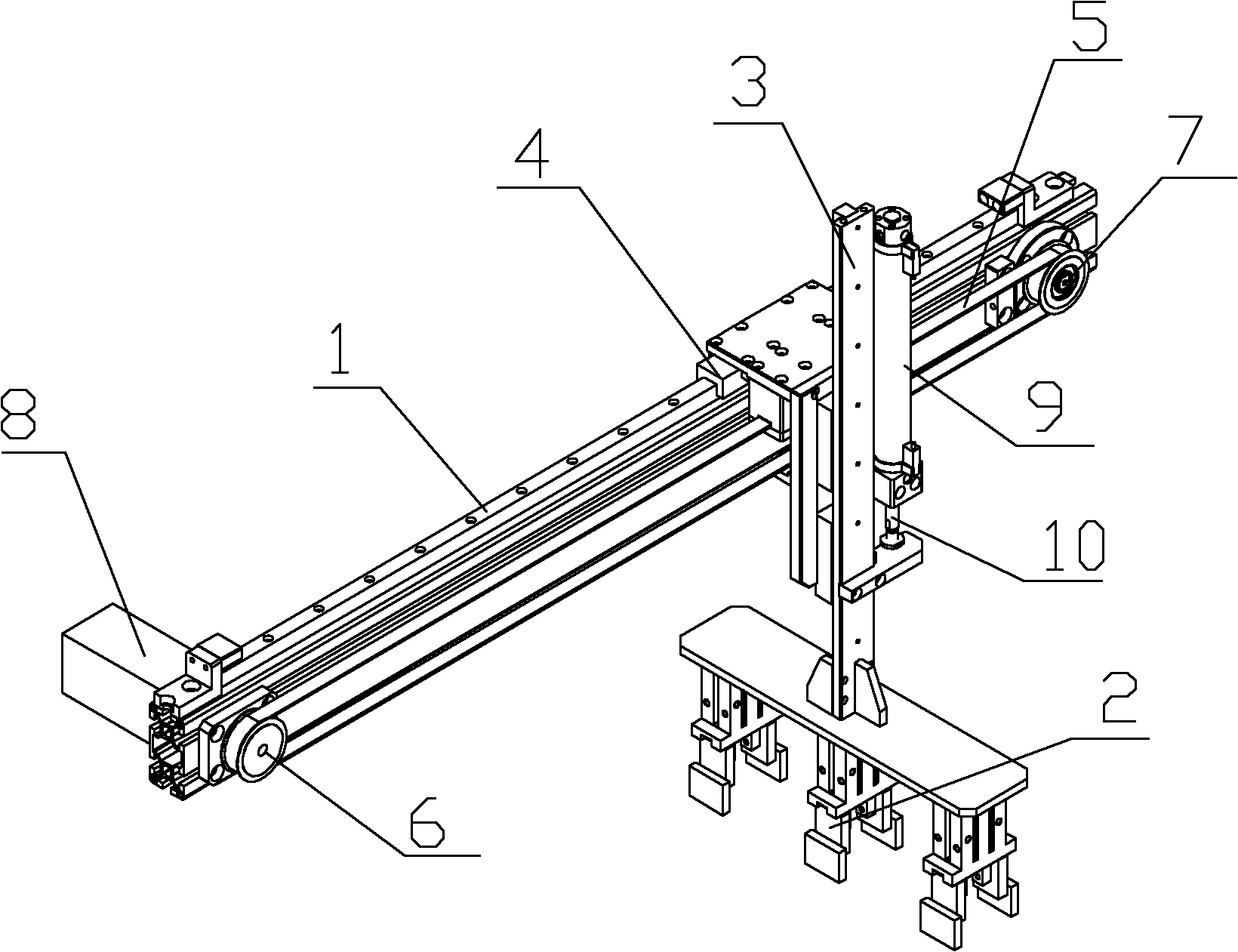
[0020] Such as figure 1 As shown, the electric energy meter handling manipulator suitable for the meter box described in this embodiment includes a frame 1 and three pneumatic grippers 2 for clamping the electric energy meter. The pneumatic grippers 2 are arranged on a longitudinal member 3 Above, the longitudinal member 3 is arranged on the guide rail of a transverse member 4 and is driven by a cylinder 9. The transverse member 4 is slidably connected to the frame 1 and has transmission teeth on it. The transverse member 4 The transmission teeth are engaged with a synchronous belt 5 toothed, and the synchronous belt 5 is sleeved on a driven wheel 7 and a driving wheel 6 connected to the motor 8, and the driving wheel 6 and the driven wheel 7 are fixed on the on rack 1. The cylinder barrel 9 of the air cylinder is vertically fixed on the transverse member 4 , and the piston rod 10 of the air cylinder is connected with the longitudinal member 3 . The bottom of the transverse ...

Embodiment 2

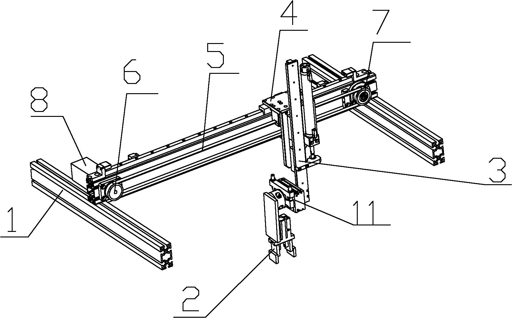
[0022] Such as figure 2 As shown, in this embodiment, a steering mechanism 11 is installed on the longitudinal member 3. The steering mechanism 11 is connected to the pneumatic gripper 2 and has a steering function to improve the flexibility of transporting the electric energy meter. In this embodiment, there is only one pneumatic gripper 2, which is suitable for the loading and unloading operation of the built-in single-row electric energy meter box.


PUM


Abstract

The invention designs an electric energy meter carrying manipulator suitable for a meter box and relates to electric energy meter moving and carrying equipment and solves the technical problem that: the conventional electric energy meter carrying manipulators are low in efficiency because of manual operation. The electric energy meter carrying manipulator comprises a frame and a pneumatic clamping jaw for clamping an electric energy meter and is characterized in that: the pneumatic clamping jaw is arranged on a longitudinal part; the longitudinal part is arranged on a vertical guide rail of a transverse part and is driven by an air cylinder; and the transverse part is connected on the frame in a sliding mode and is driven by a synchronous belt. By movement in the horizontal and vertical directions, the pneumatic clamping jaw is moved to above the electric energy meter for grabbing the electric energy meter or is moved to above a meter box for placing the meter in the meter box. The electric energy meter carrying manipulator is operated automatically. The production efficiency is improved. Manpower resources are saved. The electric energy meter can be placed into a transfer station by the manipulator and then is grabbed to a tool plate by another automatic manipulator. The influence of a tolerance of an inner die of the meter box on setting of automatic program parameters for controlling the manipulator which grabs the electric energy meter to the tool plate is eliminated by the transfer station.

Description

technical field [0001] The invention relates to electric energy meter transfer equipment, in particular to an electric energy meter handling manipulator suitable for a meter box. Background technique [0002] For the convenience of the verification of the electric energy meter, the electric energy meter is generally moved from the meter box to the tooling board for verification. After the verification and other procedures are completed, the electric energy meter is moved back from the tooling board to the meter box. At present, the above-mentioned transfer work is mostly manual operation. This working method is labor-intensive and low-efficiency, and is no longer suitable for the production needs of industrial automation. Moreover, since the electric energy meter in the meter box is placed sideways, and the electric energy meter on the tooling board must be placed horizontally, the electric energy meter in the meter box must be placed horizontally. The electric energy meter ...

Claims


Application Information

Patent Timeline
IPC IPC(8): B65G47/91
Inventor 黄金娟吴坚徐永进谢烽董强丁荣荣
Owner STATE GRID ZHEJIANG ELECTRIC POWER
Why Eureka
Try Eureka