Eureka AIR delivers breakthrough ideas for toughest innovation challenges, trusted by R&D personnel around the world.

Pressure-yielding anchor device

A technology of yielding anchors and yielding anchor rods, which is applied in the field of anchors, can solve the problems of reducing the service life of anchor cables and prone to corrosion, and achieves reliable effects and convenient manufacture

Active Publication Date: 2013-01-30
杭州图强工程材料有限公司
View PDF2 Cites 0 Cited by
  • Summary
  • Abstract
  • Description
  • Claims
  • Application Information

AI Technical Summary

Problems solved by technology

This technology is only suitable for anchor cables (steel strands), not for the yielding of thick steel anchor rods; especially since the prestressed tendons must pass through the extrusion sleeve, when the prestressed tendons use unbonded tendons, the prestressed tendons The casing must be stripped off. During the application process, this section of prestressed tendon is prone to corrosion without a protective layer, reducing the service life of the anchor cable.

Method used


Image

  • Pressure-yielding anchor device
  • Pressure-yielding anchor device
  • Pressure-yielding anchor device

Examples


Embodiment Construction

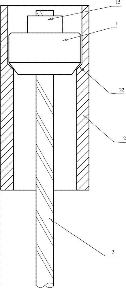
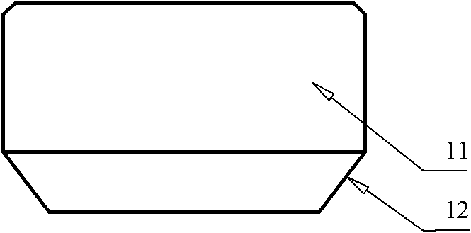
[0031] like figure 1 , figure 2 As shown, a pressure-yielding anchor device includes an extrusion head 1 and a pressure-yielding sleeve 2. The extrusion head 1 is a cylinder 11 with a tapered surface 12 on the lower part. The anchor bar 3 passes through the extrusion head 1 and passes through the The fixing part 15 is integrated with the extrusion head 1 ; the extrusion head 1 is placed in the pressure relief sleeve 2 , and the inner wall of the pressure relief sleeve 2 is provided with a protruding surface 22 matching the tapered surface 12 of the extrusion head 1 .

[0032] The cone surface 12 of the extrusion head 1 is a straight cone surface or a curved cone surface, which is continuous in a ring shape.

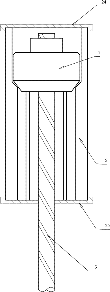
[0033] like image 3 , Figure 4 , Figure 5 As shown, the pressure relief sleeve 2 has a plurality of evenly distributed straight ribs 21 on the inner wall, and the end of the straight ribs 21 is a protruding surface 22 that matches the tapered surface 12 of the ext...


PUM


Abstract

The invention discloses a pressure-yielding anchor device, which comprises an extrusion head, a pressure-yielding sleeve and anchor bars, wherein the extrusion head is a cylinder with the conical surface at the lower part and movably connected with the anchor bars into a whole; and the extrusion head is arranged in the pressure-yielding sleeve, the raised surface matched with the conical surface at the lower part of the extrusion head is arranged on the inner wall of the pressure-yielding sleeve, the pressure-yielding sleeve is a steel pipe with a raised edge on the inner wall preferably, and the raised surface matched with the conical surface of the extrusion head is arranged at the end part of the raised edge. By adopting the pressure-yielding anchor device, the purposes of yielding pressure, dissipating energy and controlling deformation can be realized during anchoring, and the pressure-yielding anchor device is applicable to the anchor bars made of any material. The pressure-yielding anchor device is convenient to manufacture, reliable in effects and applicable to different engineering needs.

Description

technical field [0001] The invention relates to an anchorage, in particular to an anchorage with energy dissipation and deformation under force yielding, which is applied to the deformation and energy dissipation of bridges and building structures, and the anchorage of stratum rock and soil in geotechnical engineering. Background technique [0002] At present, there are more than 10 types of anchor rods or anchor cables in the field of geotechnical engineering, which have become the main means of geotechnical reinforcement. Their common stress feature is that the deformation of the anchor cable must be coordinated with the deformation of the rock and soil mass. If the deformation of the rock mass exceeds the maximum deformation allowed by the anchor cable, it will be broken. The load-bearing device that can cope with the strong shock and vibration deformation of explosions and earthquakes and can maintain a predetermined force to continue working plays a very important role ...

Claims


Application Information

Patent Timeline
Patent Type & Authority Patents(China)
IPC IPC(8): E02D5/74E01D19/14
Inventor 项小珍吕志平王勇吴航通
Owner 杭州图强工程材料有限公司
Why Eureka
Eureka Blog
Learn More