Centrfugal fan for oil and smoke exhaust machine and method for manufacturing volute profile line thereof

A technology of centrifugal fans and range hoods, which is applied in the direction of machines/engines, mechanical equipment, liquid fuel engines, etc., and can solve the deterioration of the unevenness of the airflow at the outlet of the impeller, the decrease of the air volume, air pressure and efficiency of the fan, and the uneven airflow at the outlet of the impeller and other problems, to achieve the effect of simple and reasonable volute structure, low efficiency and ingenious design

Inactive Publication Date: 2011-09-14
FOSHAN SHUNDE MIDEA WASHING APPLIANCES MFG
View PDF6 Cites 50 Cited by
  • Summary
  • Abstract
  • Description
  • Claims
  • Application Information

AI Technical Summary

Problems solved by technology

[0003] like Figure 5 As shown, the logarithmic helix J in the volute type line 1 f 1 G 1 The equation of the volute is based on "the flow of wind flowing through different sections of the volute is proportional to the angle formed between the section and the initial section of the volute (ie In the formula, Q φ is the flow of any cross-section, Q is the flow of the end cross-section)", but it is actually derived from the assumption that a part of the impeller outlet near the exit of the volute (such as Figure 5 shaded part) does not go around the logarithmic helix J 1 f 1 G 1 rotating flow, but directly from the volute outlet D 1 h 1 Therefore, the volute

Method used


Image

  • Centrfugal fan for oil and smoke exhaust machine and method for manufacturing volute profile line thereof
  • Centrfugal fan for oil and smoke exhaust machine and method for manufacturing volute profile line thereof
  • Centrfugal fan for oil and smoke exhaust machine and method for manufacturing volute profile line thereof

Examples


Embodiment Construction

[0026] The present invention will be further described below in conjunction with the accompanying drawings and embodiments.

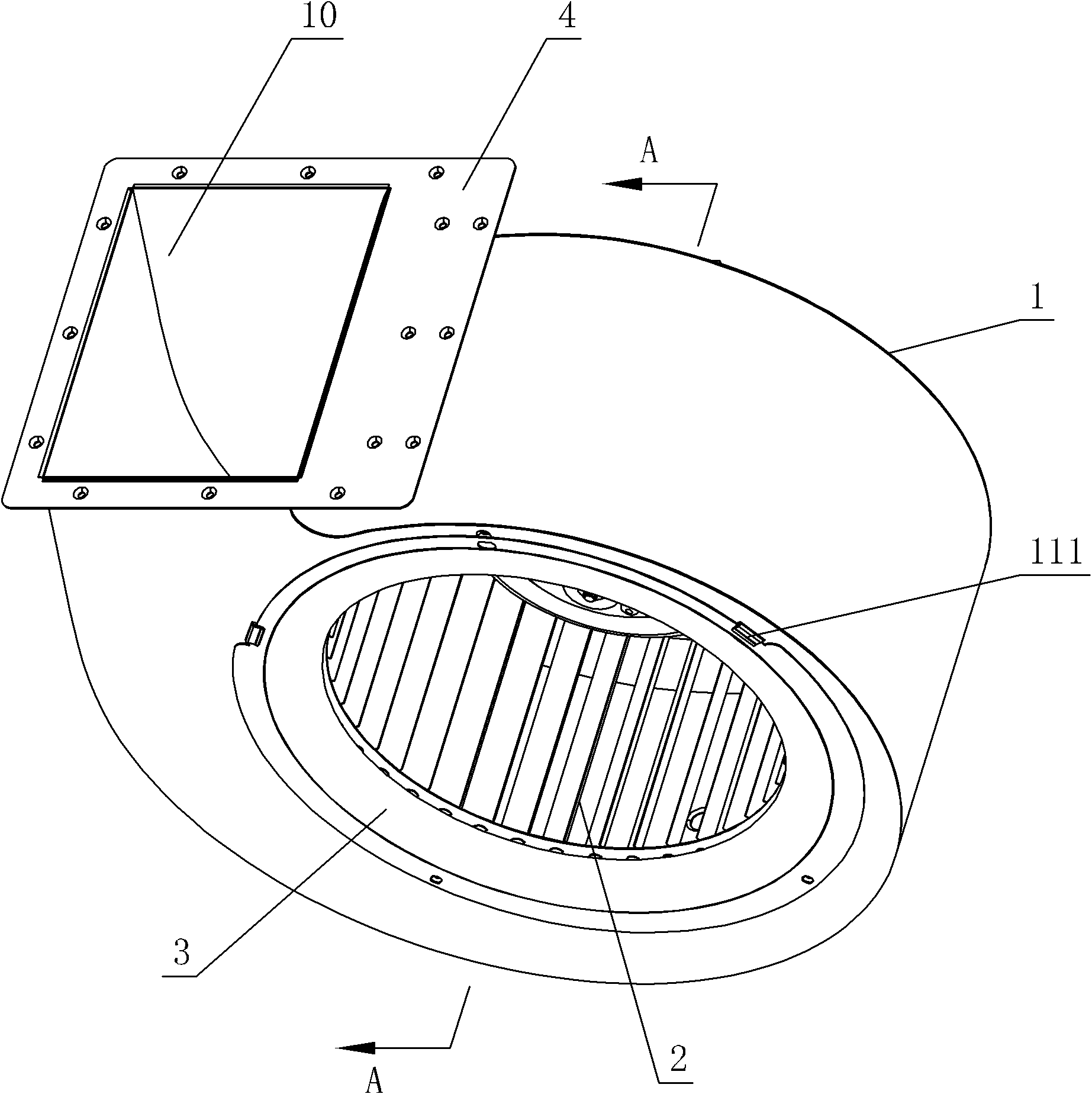
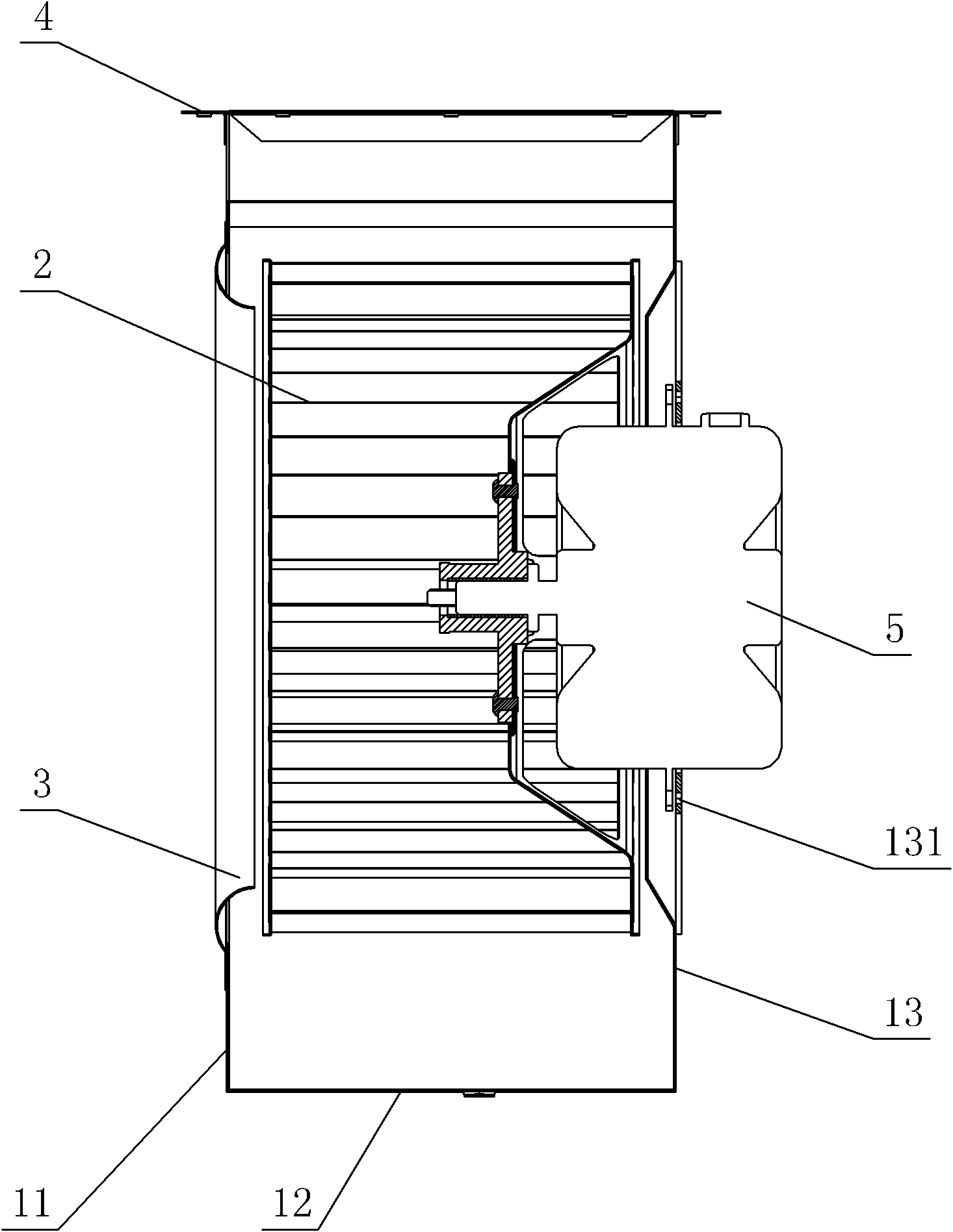
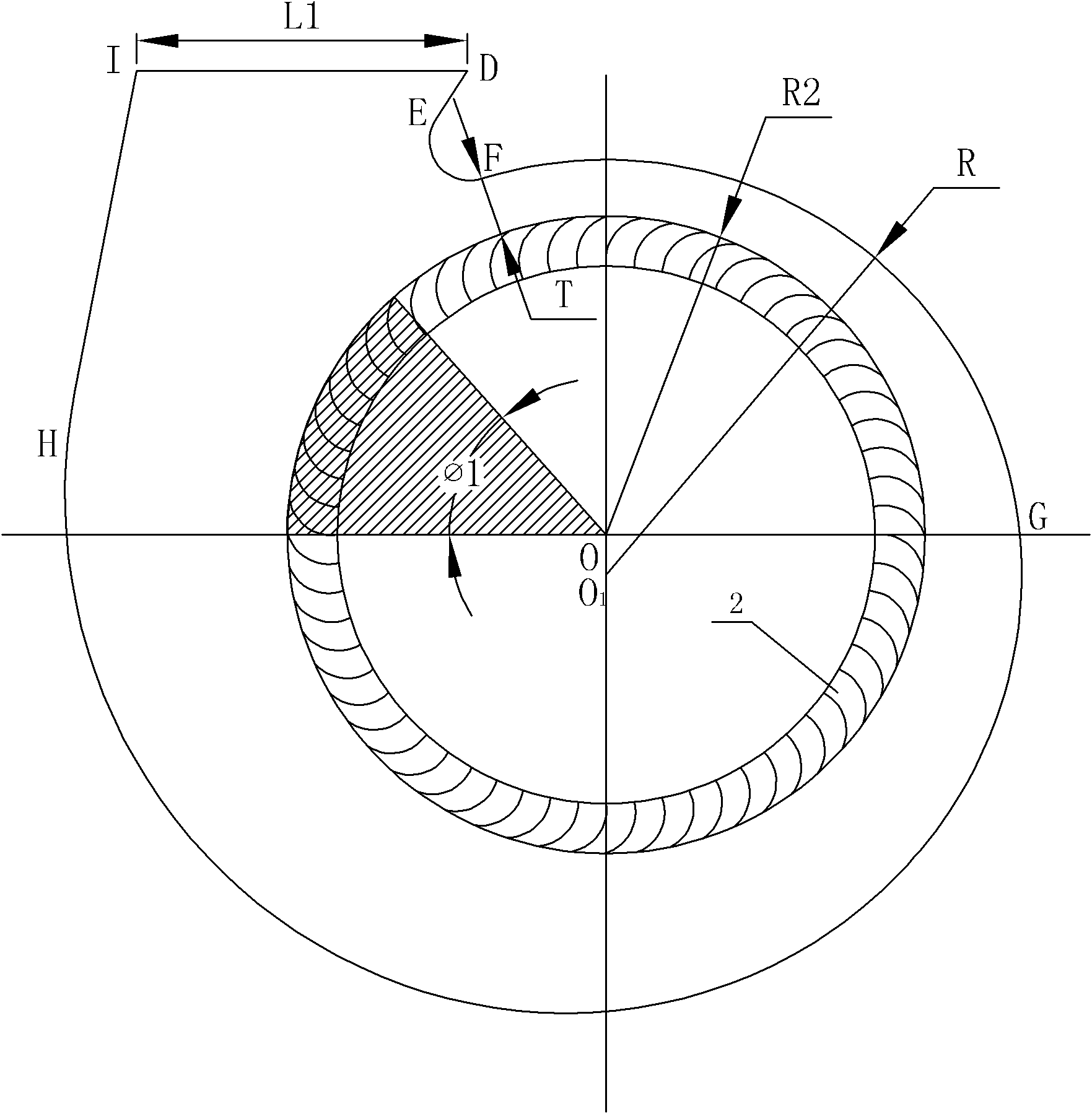
[0027] see Figure 1-Figure 2 , the centrifugal fan for the range hood, including a volute 1 provided with an air inlet and an air outlet 10, an impeller 2 arranged in the volute 1, an air inlet ring 3 arranged on the air inlet, and a motor for driving the impeller 2 to rotate 5. The volute 1 includes a volute top plate 11 , a volute coaming 12 and a volute bottom 13 , and the volute coaming 12 is connected between the volute top 11 and the volute bottom 13 . The volute coaming plate 12 is formed by smooth transition connection of the first plane, the first arc surface, the second arc surface, the spiral surface and the second plane. The helicoid is a constant velocity helicoid. The upper and lower ends of the volute coaming 12 are respectively connected to the outer edges of the volute top plate 11 and the volute bottom plate 13 by welding; the air o...


PUM


Abstract

The invention relates to a centrifugal fan for an oil and smoke exhaust machine and a method for manufacturing a volute profile line thereof. The centrifugal fan comprises a volute, a blade wheel, an air inlet ring and a motor, wherein the volute is provided with an air inlet and an air outlet; the blade wheel is arranged in the volute; the air inlet ring is arranged on the air inlet; the motor drives the blade wheel to rotate; the volute comprises a volute top plate, a volute enclosing plate and a volute base plate; and the volute enclosing plate is connected between the volute top plate and the volute base plate. The centrifugal fan is characterized in that the outline of the inner side face of the volute enclosing plate is the volute profile line, and the volute profile line is formed by the smooth transitional connection of a first straight line DE, a first arc line EF, a second arc line FG, a spiral line GH and a second straight line HI. According to the invention, after considering problems in the prior art and aiming at the characteristics of large impellor size and small volute size of the centrifugal fan for the oil and smoke exhaust machine, a design method of the volute profile line of the centrifugal fan is presented, thereby making great contribution to improving the air rate, air pressure and efficiency of the centrifugal fan for the oil and smoke exhaust machine and reducing the pneumatic noises.

Description

technical field [0001] The invention relates to a centrifugal fan used for a range hood and a method for generating a volute profile thereof. Background technique [0002] Existing centrifugal fans have been widely used in range hoods due to their advantages of large suction, low noise, and compact structure. The volute is one of the core components of the centrifugal fan. Its function is to concentrate the gas leaving the impeller, guide it to the outlet of the volute, and convert part of the dynamic pressure of the gas into static pressure. The volute shape of the centrifugal fan determines the shape of the volute, which has a great influence on the air volume, wind pressure, efficiency and aerodynamic noise of the centrifugal fan. The production method of conventional centrifugal fan volute is as follows: Figure 5 As shown, the volute profile is formed by the first straight line D 1 E. 1 , Arc E 1 f 1 , logarithmic spiral F 1 G 1 and the second straight line G 1 ...

Claims


Application Information

Patent Timeline
IPC IPC(8): F04D29/42
Inventor 梁之博丁蛟李志强季俊生黎本锋
Owner FOSHAN SHUNDE MIDEA WASHING APPLIANCES MFG
Why Eureka
Try Eureka