
Systems and methods for phasing multiple impulse cleaning devices

A cleaning device and phase adjustment technology, applied in the directions of cleaning heat transfer devices, cleaning methods and utensils, chemical instruments and methods, etc., can solve the problems of high maintenance costs of cleaning systems, different system performances, system shutdowns, etc.

Inactive Publication Date: 2011-09-14
GENERAL ELECTRIC CO
View PDF5 Cites 4 Cited by
  • Summary
  • Abstract
  • Description
  • Claims
  • Application Information

AI Technical Summary

Problems solved by technology

These known cleaning systems are costly to maintain, the effectiveness of these systems varies and some may require system downtime to perform cleaning

Method used


Image

  • Systems and methods for phasing multiple impulse cleaning devices
  • Systems and methods for phasing multiple impulse cleaning devices
  • Systems and methods for phasing multiple impulse cleaning devices

Examples


Embodiment Construction

[0017] Illustrative embodiments of the invention will be described more fully hereinafter with reference to the accompanying drawings, in which some, but not all embodiments of the invention are shown. Indeed, the invention may be embodied in many different forms and should not be construed as limited to the embodiments set forth herein; rather, these embodiments are provided so that this disclosure will satisfy applicable legal requirements. Like reference numerals denote like elements throughout.

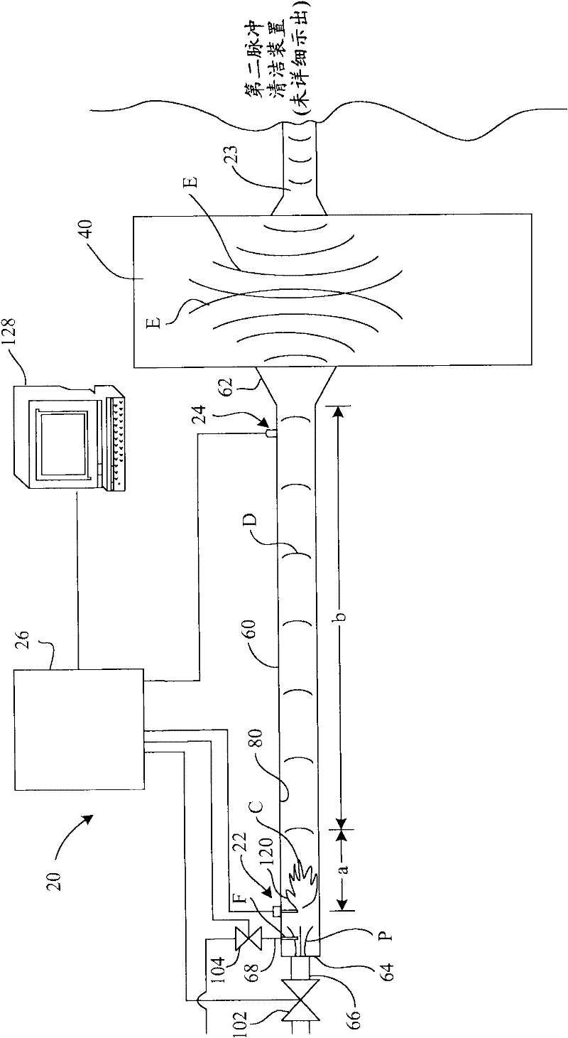
[0018] An industrial boiler is described herein as an example vessel having surfaces to be cleaned by the pulse cleaning system embodiments described herein. It will be appreciated, however, that the pulse cleaning systems and methods described herein can be used with any other surface of any vessel, machine, or other equipment, and can provide cleaning of a variety of different surfaces that may experience fouling or accumulation of debris . Accordingly, although container and / ...


PUM


Abstract

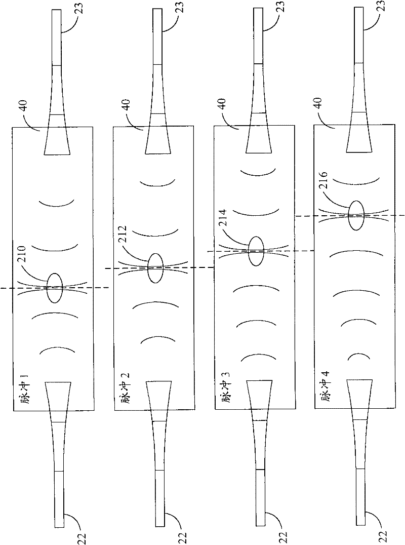
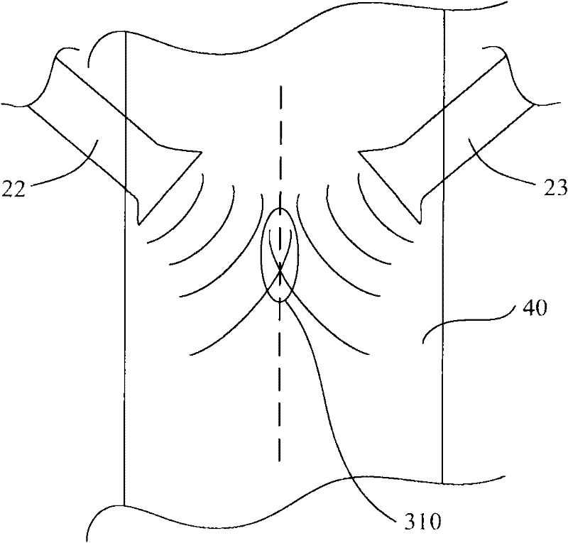
Embodiments provide systems 20 and methods 500 for removing debris from a surface. A system 20 can include a first impulse cleaning device 22 and a second impulse cleaning device 23, each impulse cleaning device generating shock waves directed to a surface to be cleaned, wherein the first impulse cleaning device and the second impulse cleaning device are oriented such that the respective shock waves intersect 210 at or proximate the surface. The system can further include a controller 26 in operable communication with the first impulse cleaning device 22 and the second impulse cleaning device 23, wherein the controller 26 is configured to selectively cause phased operation of the first impulse cleaning device 22 and the second impulse cleaning device 23 such that the phased operation selectively controls the location of the intersection 210 of the respective shock waves.

Description

technical field [0001] Embodiments of the present invention relate generally to industrial cleaning devices and, more particularly, to systems and methods for phasing multiple impulse cleaning devices. Background technique [0002] Industrial boilers work by using a heat source to generate steam from water or another working fluid, which can then be used to drive a turbine for power. The heat source may be a burner which burns a fuel to generate heat which is transferred to the working fluid via a heat exchanger. Combustion of fuel can generate residues that can be left on burner or heat exchanger surfaces. Such residues of soot, ash, slag or dust on heat exchanger surfaces can prevent heat transfer and thus reduce the efficiency of a system such as a boiler. Regular removal of such accumulated deposits maintains the efficiency of such boiler systems. [0003] Pressurized steam, water jets, sonic waves and mechanical hammering have been used to remove accumulated deposits...

Claims


Application Information

Patent Timeline
Patent Type & Authority Applications(China)
IPC IPC(8): F23J3/00
CPCF28G7/00B08B7/00F28G7/005F28G15/003B08B7/0007B08B7/02F28G11/00
Inventor D·M·查平A·J·迪恩
Owner GENERAL ELECTRIC CO
Learn More