
Nuclear magnetic resonance detection meter and detection method of hidden troubles of dam leakage

A hidden danger detector, nuclear magnetic resonance technology, applied in the direction of detecting the appearance of fluid at the leakage point, using liquid/vacuum degree for liquid tightness measurement, etc., can solve problems such as inaccuracy, improve accuracy and reduce damage to dams , the effect of improving operational efficiency

Inactive Publication Date: 2011-09-14
JILIN UNIV
View PDF5 Cites 11 Cited by
  • Summary
  • Abstract
  • Description
  • Claims
  • Application Information

AI Technical Summary

Problems solved by technology

The most important thing is that these two methods are indirect detection methods for the leakage position of the embankment, and there are certain inaccuracies

Method used


Image

  • Nuclear magnetic resonance detection meter and detection method of hidden troubles of dam leakage
  • Nuclear magnetic resonance detection meter and detection method of hidden troubles of dam leakage
  • Nuclear magnetic resonance detection meter and detection method of hidden troubles of dam leakage

Examples


Embodiment 1

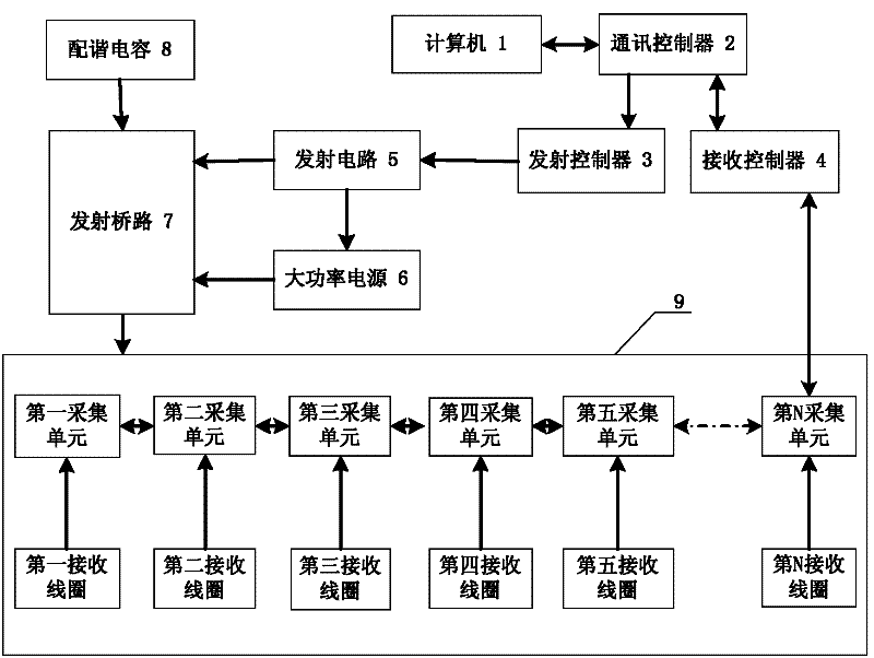
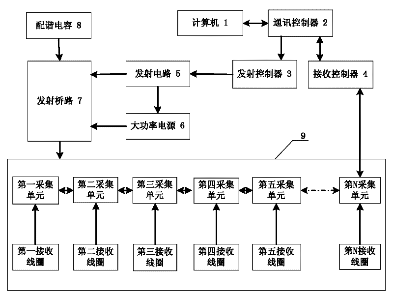
[0037] The computer 1 is connected to the communication controller 2 through a serial cable or network cable, the communication controller 2 is connected to the transmitting controller 3 and the receiving controller 4 respectively, and the transmitting controller 3 is connected to the transmitting bridge 7 through the transmitting circuit 5 and the high-power power supply 6 , the transmitting circuit 5 is connected to the transmitting bridge 7, the matching capacitor 8 is connected to the transmitting coil 9 through the transmitting bridge 7, the receiving controller 4 is connected to the Nth acquisition unit, the first acquisition unit to the Nth acquisition unit are connected in series, the first A collection unit to the Nth collection unit are connected to the corresponding first to the Nth reception coils.

[0038] The communication interface circuits 22 of the first acquisition unit to the Nth acquisition unit are connected with the communication interface 22 in the adjace...

Embodiment 2

[0049] The computer 1 is connected to the communication controller 2 through a serial cable or network cable, the communication controller 2 is connected to the transmitting controller 3 and the receiving controller 4 respectively, and the transmitting controller 3 is connected to the transmitting bridge 7 through the transmitting circuit 5 and the high-power power supply 6 , the transmitting circuit 5 is connected to the transmitting bridge 7, the matching capacitor 8 is connected to the transmitting coil 9 through the transmitting bridge 7, the receiving controller 4 is connected to the Nth acquisition unit, the first acquisition unit to the Nth acquisition unit are connected in series, the first A collection unit to the Nth collection unit are connected to the corresponding first to the Nth reception coils.

[0050] The communication interface circuits 22 of the first acquisition unit to the Nth acquisition unit are connected with the communication interface 22 in the adjace...


PUM


Abstract

The invention relates to a nuclear magnetic resonance detection meter and a nuclear magnetic resonance detection of hidden troubles of dam leakage. A transmitting controller and a receiving controller are connected to a computer through a communication controller. The transmitting controller is connected to a transmitting bridge circuit through a transmitting circuit and a large power supply. A first collecting unit is in a series connection with a second, a third... and an Nth collecting unit, and the first, the second... and the Nth collecting unit are respectively connected to a first, a second... and an Nth receiving coil. The receiving controller is connected to the Nth collecting unit. Multi-turn rectangular transmitting coils are disposed on the top of a dam and the receiving coilsare used to receive signals. Once the receiving coils collect nuclear magnetic resonance response signals, that dam leakage exists can be proved, and a water distribution map of the dam can be drawn after the signal data is processed, so as to determine a leakage location. By adopting nuclear magnetic resonance to detect hidden troubles of dam leakage and measuring the inner water content of the dam directly, the leakage location of the dam can be determined more precisely, thereby reducing damages to the dam in the detection maximally and adding no new potential safety hazard any more. Moreover, the whole detection can be completed on the top of the dam. The detection meter and the detection method are convenient for detecting operation.

Description

technical field [0001] The invention relates to geophysical detection equipment used in water conservancy projects, in particular to a detection device and detection method for hidden dangers of dam leakage based on nuclear magnetic resonance technology. Background technique [0002] Magnetic Resonance Sounding (MRS for short) is a direct and non-destructive geophysical exploration method. [0003] CN101858991A discloses a system and method for detecting the position of a dam leakage channel using temperature as a tracer. The system of the invention includes N temperature sensors, a signal acquisition device, a signal fusion processing device, a control system and a data terminal device; N temperature sensors are evenly distributed in the dam body of the embankment and are respectively connected to the signal acquisition device, and the signal acquisition device, the signal fusion processing device, the control system and the data terminal device are connected in series at o...

Claims


Application Information

Patent Timeline
IPC IPC(8): G01M3/04
Inventor 段清明蒋川东林君李姗姗易晓峰田宝凤
Owner JILIN UNIV
Learn More