Threaded joint for steel pipes

A technology for threaded joints and steel pipes, applied in the direction of threaded connections, pipes/pipe joints/pipes, drill pipes, etc., can solve the problems of reduced contact area, deterioration of contact stability, etc., and achieve the effect of reducing micro-wear

Active Publication Date: 2011-09-14
NIPPON STEEL CORP +1
View PDF8 Cites 4 Cited by
  • Summary
  • Abstract
  • Description
  • Claims
  • Application Information

AI Technical Summary

Problems solved by technology

like Figure 5 As shown in (B), when the sealing surface of the box is a curved surface (R) and the sealing surface of the pin is a tapered surface, the

Method used


Image

  • Threaded joint for steel pipes
  • Threaded joint for steel pipes
  • Threaded joint for steel pipes

Examples


Embodiment

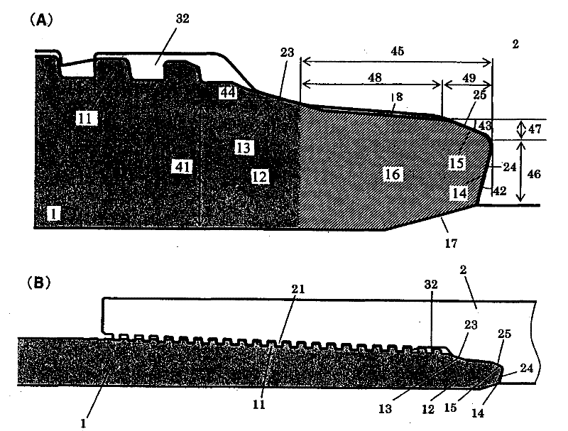
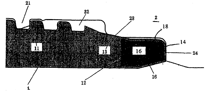
[0067] To illustrate the effect of the present invention, the ISO 13679 test was carried out on a threaded joint for casing measurements with a diameter of 9-5 / 8 inches and a weight of 53.5 pounds per foot (244.48 mm outside diameter, 13.84 mm wall thickness). Series A tests. Pins are formed on the outside of both ends of the steel pipe, and boxes are formed on the inside of both sides of the pipe joint. Threaded joints made of L80 steel (carbon steel) specified in the API (American Petroleum Institute) standard for this test have, in addition to the shape of the lip, Figure 7 The basic shape of the threaded joint for pipe joints used in the petroleum industry is shown, the lip of the threaded joint has a figure 1 (A) or figure 2 The extended lip of the shape shown includes, for each of the pin and box, a sealing surface, a shoulder surface, and a non-contact area between the sealing surface and the shoulder surface. The bevel angle of the tapered surface (portion) of the...


PUM


Abstract

In a threaded joint for steel pipes comprising a pin (1) and a box (2), each having a threaded portion (11 or 21), a sealing surface (13 or 23), and a shoulder surface (14, 15 or 24, 25), the sealing surface (13) of the pin (1) is formed by a tapered surface, and the sealing surface (23) of the box (2) is formed by a first curved surface portion with a large radius of curvature in the range of 15- 120 mm, a tapered surface portion, and a second curved surface portion with a large radius of curvature again in the range of 15 - 120 mm.

Description

technical field [0001] The present invention generally relates to a threaded joint for connecting steel pipes such as oil industry tubular goods (OCTG), risers, mainline pipes, etc., including those used in the exploration and production of crude oil and natural gas. Tubing and casing. More particularly, the present invention relates to a threaded joint for steel pipes having a threaded portion, a sealing surface, and a shoulder surface, and having excellent pressure-resistant sealing performance. Background technique [0002] A threaded joint for steel pipes widely used to connect steel pipes used in oil production industrial equipment such as oil industry pipes and standpipes consists of a pin and a box. A male or external threaded element at the end of the member, the box is an element with a female or internal thread provided at the end of the second tubular member. The connection of threaded joints is achieved by the threaded engagement of male and female threads, bot...

Claims


Application Information

Patent Timeline
IPC IPC(8): F16L15/04
CPCE21B17/042F16L15/004
Inventor 冈田隆志中村圭一杉野正明山口优
Owner NIPPON STEEL CORP
Why Eureka
Try Eureka