Slurry pump

A slurry pump and pump casing technology, applied in the field of feed pumps, can solve the problems of large material flow resistance, large energy consumption, high shaft power requirements, etc., and achieve the effect of reducing resistance and reducing shaft power

Active Publication Date: 2013-03-20
李国中
View PDF3 Cites 4 Cited by
  • Summary
  • Abstract
  • Description
  • Claims
  • Application Information

AI Technical Summary

Problems solved by technology

[0002] At present, in the secondary feed pump used in the filter press in the coal washing industry, the communication pipe between the primary impeller and the secondary impeller is arranged perpendicular to the axis of the primary impeller shell, so the material flow resistance is large, the shaft power requirement is high, and the energy consumes a lot

Method used


Image

  • Slurry pump
  • Slurry pump
  • Slurry pump

Examples


Embodiment Construction

[0018] Below in conjunction with accompanying drawing, the present invention is described in further detail:

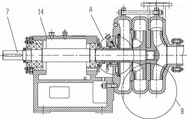
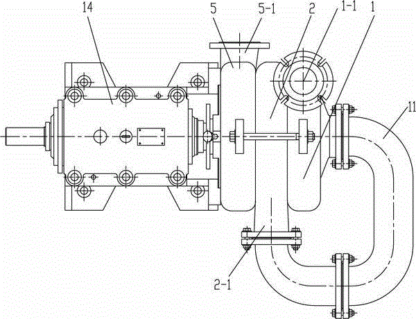
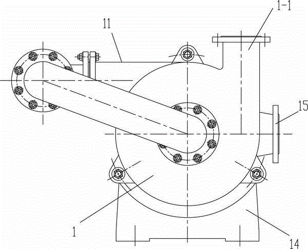
[0019] figure 1 , 2 , 3, 4 or 5, the present invention includes a bracket 14, the bracket 14 supports the pump body, the pump body includes the impeller, the main shaft 7 and the pump casing, the pump casing is fixed on the front end of the bracket 14, and the bracket 14 is supported by the rotary pair The main shaft 7, the front end of the main shaft 7 is assembled with the impeller arranged in the inner cavity of the pump casing, and the end is connected to the motor through a coupling. The pump casing includes a suction chamber 5, a primary pump casing 2 and a secondary pump casing 1, all of which are cylindrical The end faces of the casing are connected end to end in turn. The first-stage impeller 4 is arranged in the first-stage pump casing 2, and the second-stage impeller 3 is arranged in the second-stage pump casing 1. The first and second-stage impellers 4 an...


PUM


Abstract

The invention relates to a slurry pump, in particular to a charging pump used for a press filter in coal washing industry. The slurry pump comprises a bracket for supporting a pump body, wherein the pump body comprises an impeller, a main shaft and a pump shell. The slurry pump is characterized in that: the pump shell comprises a suction chamber, a primary pump shell and a secondary pump shell connected in turn end to end, wherein a primary impeller is arranged in the primary pump shell; a secondary impeller is arranged in the secondary pump shell; the primary impeller and the secondary impeller are arranged relatively; the side wall of the suction chamber is provided with a feed port; the tail end face of the suction chamber is provided with a suction chamber outlet; the suction chamber outlet is communicated with a primary pump shell inlet formed on the front end face of the primary pump shell; the side wall of the primary pump shell is provided with a primary pump shell outlet of which the direction is arranged along the tangential direction of the wall of the primary pump shell; the primary pump shell outlet is communicated with a secondary pump shell inlet formed on the outer end face of the secondary pump shell; the side wall of the secondary pump shell is provided with a discharge port; and the direction of the primary pump shell outlet is arranged along the tangential direction of the wall of the pump shell. Thus, the slurry pump accords with water conservation characteristics of fluid, reduces the resistance of the fluid in a pump body cavity, and is favorable for reducing the shaft power.

Description

[0001] The invention relates to a slurry pump, in particular to a feed pump used for a filter press in the coal washing industry. Background technique [0002] At present, in the secondary feed pump used in the filter press in the coal washing industry, the communication pipe between the primary impeller and the secondary impeller is arranged perpendicular to the axis of the primary impeller shell, so the material flow resistance is large, the shaft power requirement is high, and the energy It consumes a lot. Contents of the invention [0003] The technical problem to be solved in the present invention is to provide a slurry pump, which can reduce material flow resistance, shaft power and energy consumption by improving the structure of the existing pump body. [0004] In order to solve the above technical problems, the technical solution adopted in the present invention is: a slurry pump, a bracket, the bracket supports the pump body, the pump body includes an impeller, a m...

Claims


Application Information

Patent Timeline
Patent Type & Authority Patents(China)
IPC IPC(8): F04D29/22F04D29/42F04D29/08
Inventor 李国中
Owner 李国中
Why Eureka
Try Eureka