
Coupling element for connecting the ends of two tubes

A technology for connecting components and connecting ends, applied in the field of connecting components

Inactive Publication Date: 2011-09-21
NORMA GERMANY GMBH
View PDF8 Cites 3 Cited by
  • Summary
  • Abstract
  • Description
  • Claims
  • Application Information

AI Technical Summary

Problems solved by technology

[0006] However, the use of the cover requires operator action

Method used


Image

  • Coupling element for connecting the ends of two tubes
  • Coupling element for connecting the ends of two tubes
  • Coupling element for connecting the ends of two tubes

Examples


Embodiment Construction

[0044] The particulars presented here are exemplary and used for illustrative discussion of embodiments of the invention only, and are presented to provide what is believed to be the most useful and understandable description of the principles and conceptual aspects of the invention. Regarding this point, there is no attempt to introduce the structural details of the present invention beyond the level required for a basic understanding of the present invention. Those skilled in the art can clearly understand how to implement the present invention in practice through the description and accompanying drawings. Several forms.

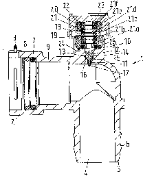
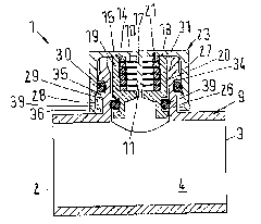
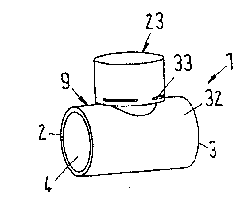
[0045] figure 1 A cross-section of a connection element 1 is shown, comprising a first connection end 2 , a second connection end 3 , and a connection channel 4 implemented or formed between them. Thus, liquid can be guided through the connecting element 1 or the connecting channel 4 . The connection end 2 is embodied or formed as an insertion end such ...


PUM


Abstract

Coupling element for connecting the ends of two tubes. The coupling element includes a housing with a first connecting end, a second connecting end, and a connecting channel formed between the first and second connecting ends, and a vent duct having a passage covered by a hygroscopic seal and a vent valve that includes a valve seat and a valve element arranged in series with the hygroscopic seal and the passage. The valve element is structured to be lifted from the valve seat by a pressure in the connecting channel.

Description

[0001] Cross References to Related Applications [0002] Pursuant to Title 35, United States Code, Section 119, this patent application claims priority to German Patent Application 102010010463.9, filed March 6, 2010, and German Patent Application 102010015157.2-24, filed April 16, 2010, which The entire disclosure is expressly incorporated herein by reference. technical field [0003] The invention relates to a connecting element for connecting two pipe ends, in particular in a coolant circuit of a motor vehicle, comprising a housing with a first connecting end and a second connecting end and The discharge pipe is provided or formed with a connecting channel between the two connecting ends. Background technique [0004] Such connecting elements can be used in the production of piping systems in order to connect individual pipe ends to one another, but can also be used, for example, to form branches or to introduce control elements such as valves or closable openings into ...

Claims


Application Information

Patent Timeline
Patent Type & Authority Applications(China)
IPC IPC(8): F16L55/07
CPCF16K24/06F16L55/07F16K24/04F16K25/02F16K27/00
Inventor 安德烈亚斯·鲍尔杰罗姆·夏读
Owner NORMA GERMANY GMBH
Learn More