
Three-dimensional panorama head

A panoramic pan-tilt and three-dimensional technology, applied in the direction of machines/supports, optics, instruments, etc., can solve the problems that cannot meet this requirement, and achieve the effect of simple structure, precise adjustment and positioning, and low manufacturing cost

Inactive Publication Date: 2011-09-21
上海高弗特实业集团有限公司
View PDF9 Cites 31 Cited by
  • Summary
  • Abstract
  • Description
  • Claims
  • Application Information

AI Technical Summary

Problems solved by technology

[0005] Obviously, the existing gimbals including the above-mentioned patents cannot meet this requirement

Method used


Image

  • Three-dimensional panorama head
  • Three-dimensional panorama head
  • Three-dimensional panorama head

Examples


Embodiment Construction

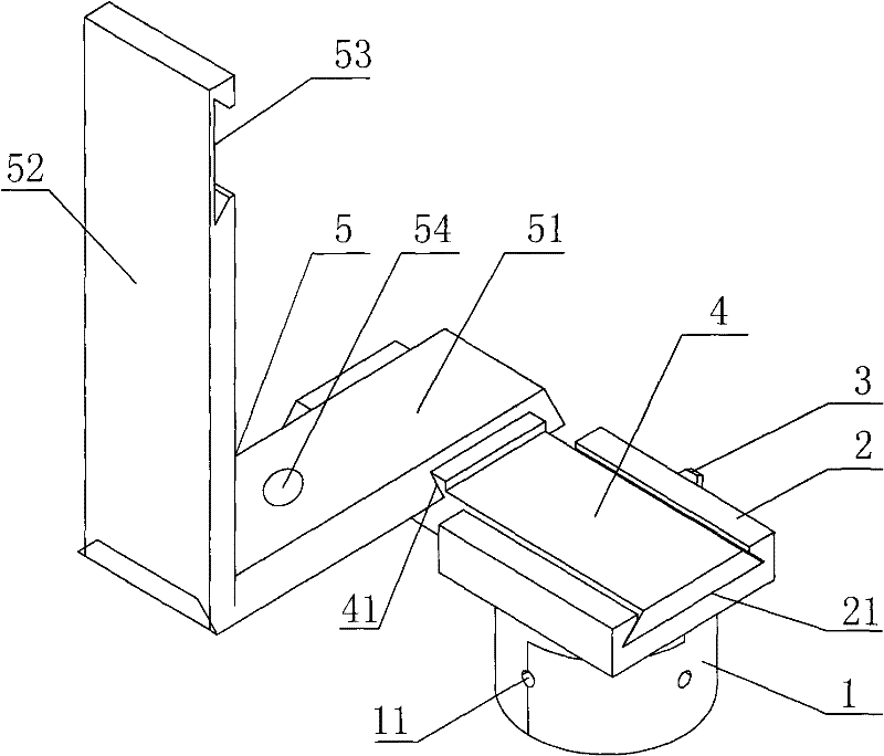
[0025] Such as figure 1 As shown, a three-dimensional panorama platform according to the present invention includes a horizontal rotation seat 1 , a horizontal slide rail 4 and an L-shaped bracket 5 . The L-shaped bracket 5 is formed by vertically connecting the first arm plate 51 and the second arm plate 52. The first arm plate 51 is provided with a compass 54 near the connecting corner, and the top of the second arm plate 52 is provided with a camera holder 53. For mounting a fixed camera.

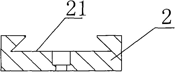
[0026] Wherein, the horizontal rotating seat 1 is cylindrical, and the side wall of the horizontal rotating seat 1 is provided with four positioning holes 11 uniformly distributed along the circumference, evenly distributed at intervals of 90 degrees, and the horizontal rotating seat 1 is provided with spring balls and the positioning holes. 11 to accurately define the four rotational positions of the horizontal rotating base 1. A chute seat 2 is also fixed on the top of the horizontal...


PUM


Abstract

The invention discloses a three-dimensional panorama head which comprises a horizontal rotary seat and an L-shaped bracket, wherein the L-shaped bracket is composed of a first arm board and a second board which are vertically connected with each other, the top of the horizontal rotary seat is provided with a lateral chute, a horizontal slide rail is arranged in the lateral chute, a longitudinal chute is arranged on the horizontal slide rail, the first arm board of the L-shaped bracket is in sliding fit with the longitudinal chute, a compass is arranged close to the corner of the first arm board, and the top of the second arm board of the L-shaped bracket is provided with a camera fixing seat. The three-dimensional panorama head provided by the invention has a simple structure, is convenient to use and carry, can adjust positioning more accurately and well satisfy a 360-degree panoramic shot in the horizontal direction for single lens reflex cameras of various types.

Description

technical field [0001] The invention relates to a photographic equipment, in particular to a cloud platform which can be used for three-dimensional panoramic photography. Background technique [0002] The camera head is generally installed on a tripod for fixing the camera and can be rotated 360 degrees for panoramic photography. [0003] Chinese Utility Model Patent No. 200920090390.0 discloses a multifunctional panorama platform, which includes a longitudinal rotating platform, a horizontal rotating platform and a main support. The plate connecting bolts are fixed on the folding plate frame, and there is a mounting hole at the other end of the folding plate. The scale and the folding plate frame are fixed on the main bracket through the longitudinal locking handle; the quick release plate base is installed on the end of the folding plate slide rod through the connection hole below it, and is fastened by a fastening bolt. There is a concave hole on the quick release plate ...

Claims


Application Information

Patent Timeline
IPC IPC(8): F16M11/04G03B17/56
Inventor 徐怡北
Owner 上海高弗特实业集团有限公司
Learn More