Energy-saving environmentally-friendly boiler

An energy-saving and environmental-friendly boiler technology, applied in the field of boilers, can solve the problems of poor overall effect of energy-saving and environmental protection, poor combustion effect of boilers, etc., and achieve good combustion effect, strong fire and full combustion

Inactive Publication Date: 2011-09-21
鞍山市红运锅炉制造有限公司
View PDF5 Cites 2 Cited by
  • Summary
  • Abstract
  • Description
  • Claims
  • Application Information

AI Technical Summary

Problems solved by technology

[0003] The purpose of the present invention is to provide an energy-saving and environment-friendly boiler, which solves the problems existing

Method used


Image

  • Energy-saving environmentally-friendly boiler
  • Energy-saving environmentally-friendly boiler
  • Energy-saving environmentally-friendly boiler

Examples


Embodiment 1

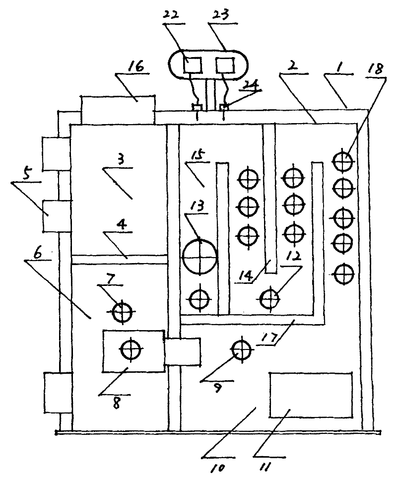
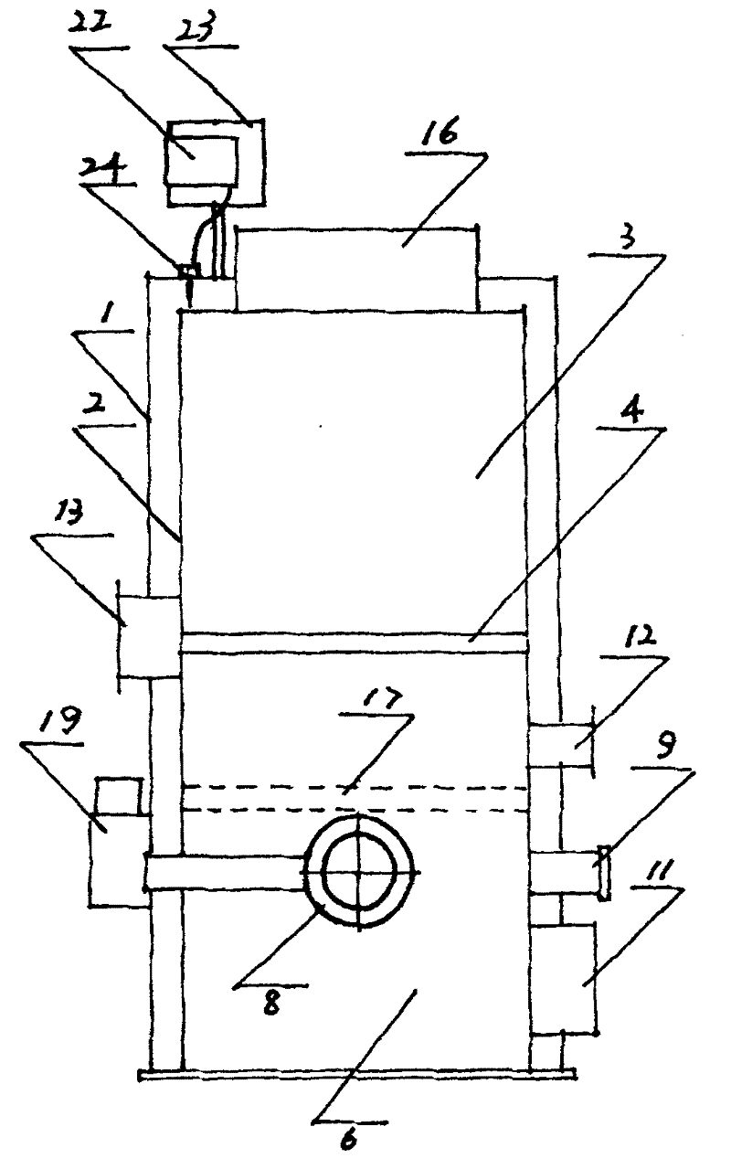
[0020] Such as Figure 1-2 As shown, the energy-saving and environmentally friendly boiler in this embodiment is suitable for biofuels, mainly including: furnace body 1, furnace 2, combustion chamber 3, fire grate 4, furnace door 5, gasification chamber 6, observation hole 7, jet combustion device 8 , observation hole 9, gas combustion chamber 10, side furnace door 11, soot cleaning hole 12, induced draft fan outlet 13, interlayer partition 14, combustion process combustion chamber 15, feeding port 16, interlayer top plate 17, hot water tube bundle 18, suction and discharge Port 19, display instrument 22, instrument box 23, sensor 24, etc. Furnace body 1 is provided with furnace chamber 2, a water interlayer is formed between furnace body 1 and furnace chamber 2, and furnace chamber 2 is provided with combustion chamber 3 and gasification chamber 6. Gas combustion chamber 10 and process combustion chamber 15. The combustion chamber 3 and the gasification chamber 6 are arranged...

Embodiment 2

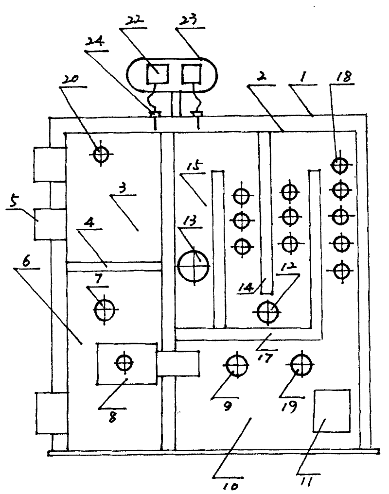
[0029] Such as Figure 3-4 As shown, the energy-saving and environment-friendly boiler in this embodiment is suitable for burning coal, and mainly includes: furnace body 1, furnace gall 2, combustion chamber 3, fire grate 4, furnace door 5, gasification chamber 6, observation hole 7, injection and suction hole type Oxygen supply and exhaust injection combustion device 8, observation hole 9, gas combustion chamber 10, side furnace door 11, soot cleaning hole 12, induced draft fan port 13, interlayer partition 14, process combustion chamber 15, interlayer top plate 17, hot water tube bundle 18. Suction and discharge port 19, air supply hole 20, air storage box 21, display instrument 22, instrument box 23, sensor 24, etc. Furnace body 1 is equipped with furnace 2, and a water interlayer is formed between furnace body 1 and furnace 2, and the furnace A combustion chamber 3 , a gasification chamber 6 , a gas combustion chamber 10 and a process combustion chamber 15 are arranged in ...


PUM


Abstract

The invention belongs to the field of boilers, particularly relates to an energy-saving environmentally-friendly boiler, solving the problems such as poor energy-saving and environmentally-friendly comprehensive effects, poor boiler combustion effect and the like in the prior art. A gasifying chamber, a gas combustion chamber and a flow combustion chamber are arranged in a boiler furnace of the boiler, wherein the gasifying chamber is arranged at the lower part of one side in the boiler furnace, the flow combustion chamber and the gas combustion chamber are arranged at the other side in the boil furnace with one being arranged above the other and are communicated with each other, an oxygen feeding and exhausting jet burner is arranged in the gasifying chamber and communicated with the gascombustion chamber. According to the invention, after being fully mixed with air or oxygen introduced through an intake and exhausting opening, smoke, gas and fire enter the gas combustion chamber for further fully combusting; and after the smoke, gas and fire are fully combusted in a baffled flue in the flow combustion chamber and energy is used fully, the smoke, gas and fire are discharged, thereby energy-saving environmentally-friendly effects are achieved.

Description

technical field [0001] The invention belongs to the field of boilers, in particular to an energy-saving and environment-friendly boiler. Background technique [0002] At present, the combustion methods of hand-fired boilers in my country are divided into two modes: forward combustion and reverse combustion. Forward combustion is easy to produce black smoke, the environmental protection effect is not good, and energy is wasted; the effect of reverse combustion is better when using coal blocks, but because of natural ventilation, burning surface coal will not work, and the coal in the reverse combustion chamber must be filled up, because the coal seam is too thick If the wind cannot get in, the combustion effect of the boiler is not good. Contents of the invention [0003] The object of the present invention is to provide an energy-saving and environment-friendly boiler, which solves the problems existing in the prior art, such as poor comprehensive effect of energy-saving ...

Claims


Application Information

Patent Timeline
IPC IPC(8): F23B10/02F23B80/04
Inventor 陈喜春
Owner 鞍山市红运锅炉制造有限公司
Why Eureka
Try Eureka