Wind turbine and method for measuring the pitch angle of a wind turbine rotor blade

A technology of wind turbines and rotor blades, which is applied in the control of wind turbines, monitoring of wind turbines, and wind turbines, etc. It can solve problems such as the inability to adjust the pitch angle and provide inspections, and achieve the effect of reducing vibration and load and avoiding power generation

Inactive Publication Date: 2011-09-21
SIEMENS GAMESA RENEWABLE ENERGY AS
View PDF4 Cites 15 Cited by
  • Summary
  • Abstract
  • Description
  • Claims
  • Application Information

AI Technical Summary

Problems solved by technology

However, if the zero-bar is not installed correctly, or if it is damaged, it cannot provide a check of the pitch adjustment

Method used


Image

  • Wind turbine and method for measuring the pitch angle of a wind turbine rotor blade
  • Wind turbine and method for measuring the pitch angle of a wind turbine rotor blade
  • Wind turbine and method for measuring the pitch angle of a wind turbine rotor blade

Examples


Embodiment Construction

[0039] will now refer to Figure 1 to Figure 3 A first embodiment of the present invention is described.

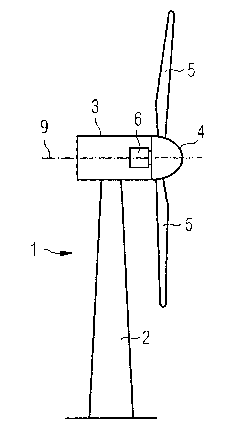
[0040] figure 1 A wind turbine 1 is shown schematically. The wind turbine 1 comprises a tower 2 , a nacelle 3 and a hub 4 . The nacelle 3 is located on top of the machine tower 2 . The hub 4 comprises three wind turbine blades 5 . However, the invention should not be limited to blades for only three-blade rotors. In fact, it can also be implemented into other rotors, such as single-blade rotors, double-blade rotors or wit rotors with more than three blades. The hub 4 is mounted to the nacelle 3 . Furthermore, the hub 4 is pivotally mounted such that it can rotate about an axis of rotation 9 . The azimuth angle represents the rotation of the rotor blade 5 about the axis of rotation 9 . The generator 6 is located in the nacelle 3 .

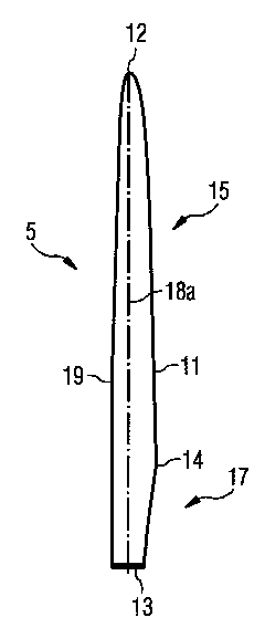
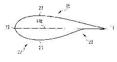
[0041] figure 2 The rotor blade is shown in terms of blade span 18a and blade chord 18b (see image 3 ) on a plane defined by . ...


PUM


Abstract

The invention relates to a wind turbine and a method for measuring the pitch angle of a wind turbine rotor blade. Concretely, a method for measuring the pitch angle of a wind turbine rotor blade is provided. In the method at least one image of at least part of the rotor blade is acquired by a camera from a defined position and the pitch angle is calculated by means of data from the at least one image.

Description

technical field [0001] The present invention relates to a method for measuring the pitch angle (or pitch angle) of a rotor blade of a wind turbine. It further relates to a wind turbine. Background technique [0002] The manufacture and installation of a wind turbine rotor, including the blades, hub and pitch system, involves several operations where tolerances can be exceeded. A wind turbine operating with blade pitch imbalance (also known as aerodynamic imbalance) may experience overloading of certain components such as the yaw system, main shaft, main shaft bearings, blade roots, and pitch system. Also, the amount of power generation may not be optimal. [0003] Pitch adjustment depends on the position of the zero degree indicators installed in the blades from the factory. However, if the zero-bar is not installed correctly, or if it is damaged, it cannot provide a check of the pitch adjustment. [0004] If the aerodynamic imbalance of the rotor is small, the additiona...

Claims


Application Information

Patent Timeline
Patent Type & Authority Applications(China)
IPC IPC(8): G01B11/26F03D1/00
CPCF05B2270/8041Y02E10/723Y02E10/722F03D11/0091F03D7/0224F05B2270/328F03D17/00Y02E10/72
Inventor I·弗里登达尔
Owner SIEMENS GAMESA RENEWABLE ENERGY AS
Why Eureka
Try Eureka