
Magnetic sensor

A magnetic sensor and magnetic field technology, applied in the field of magnetic sensors, can solve the problems of large coercive force Hc, measurement error of magnetic field strength, and inability to measure external magnetic fields normally, and achieve the effect of improving measurement performance and realizing miniaturization.

Active Publication Date: 2011-09-21
TDK CORPARATION
View PDF7 Cites 2 Cited by
  • Summary
  • Abstract
  • Description
  • Claims
  • Application Information

AI Technical Summary

Problems solved by technology

[0007] However, the spin valve type MR element not only has the above-mentioned outstanding linear characteristics, but also has the characteristics of large coercive force Hc and hysteresis
Therefore, when the above-mentioned magnetic balance method is applied, if an overshoot of the control current occurs, there is a problem that the external magnetic field cannot be measured normally.
That is, if the MR element reaches primary magnetization saturation due to overshooting, the magnetic field detection process is performed on a track part different from the original one on the hysteresis curve due to the influence of the history, so that an approximately coercive force Hc is generated. Measurement error of magnetic field strength

Method used


Image

  • Magnetic sensor
  • Magnetic sensor
  • Magnetic sensor

Examples


Embodiment Construction

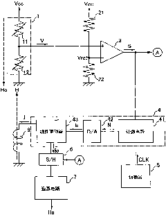
[0028] figure 1 is a circuit diagram of the magnetic sensor of the present invention. The magnetic sensor includes a magnetoresistance effect element circuit 1 (hereinafter referred to as MR element circuit 1), resistors 21 and 22 for voltage division, a voltage detection unit 3, a current control unit 4, an oscillator (Oscillator) 5, and a sample-and-hold circuit (S / H) 6, arithmetic circuit (arithmetic circuit) 7 and coil 8.

[0029] In this circuit, as in the magnetic balance method described above, the current I flowing through the coil 8 is controlled by the current control unit 4, and the magnetic field Ho to be measured around the MR element circuit 1 is canceled by the coil magnetic field H for measurement generated thereby. Based on the current value Io at this time, the intensity of the magnetic field Ho to be measured is detected. Firstly, the structure and function of the circuit are explained, and then the details of current control are explained.

[0030] The ...


PUM


Abstract

A magnetic sensor includes a spin valve-type magneto-resistive element, a voltage detection part, a coil, and a current control part, the coil being configured to apply a measuring magnetic field to the spin valve-type magneto-resistive element upon application of a current, the voltage detection part being configured to output a detection signal to the current control part upon detecting an output voltage of the spin valve-type magneto-resistive element reaching a predetermined voltage value, the current control part being configured to control the current to unidirectionally increase or unidirectionally decrease a strength of the measuring magnetic field from an initial value, but upon input of the detection signal, control the current to return the strength of the measuring magnetic field to the initial value, the initial value being a magnetic field strength where the spin valve-type magneto-resistive element reaches saturation magnetization.

Description

technical field [0001] The present invention relates to a magnetic sensor utilizing a spin valve type magnetoresistance effect element. Background technique [0002] In recent years, current sensors using magnetoresistance effect elements (MR elements) have attracted attention. Since the current sensor can detect a DC magnetic field, it can be applied to a wide range of fields such as battery control of a hybrid vehicle. [0003] Originally, the linear characteristics of the MR element were not outstanding, and in addition, it had a characteristic that the effective sensitivity range for detecting an external magnetic field was narrow. Therefore, when the MR element is applied to a magnetic sensor, as disclosed in Japanese Patent Application Laid-Open No. 10-319103 and Japanese Patent Laid-Open No. 6-294853, it is necessary to operate the MR element by applying a bias magnetic field, for example. Points are displaced toward regions with good linear properties. However, ac...

Claims


Application Information

Patent Timeline
Patent Type & Authority Applications(China)
IPC IPC(8): G01R33/02G01D5/14
CPCG01R33/093G01R33/0029B82Y25/00
Inventor 太田尚城平林启酒井正则永沼宙
Owner TDK CORPARATION
Learn More