Imaging lens with variable focus distance

An imaging lens and focal length technology, applied in optical components, optics, instruments, etc., can solve problems such as inconvenience, and achieve the effect of reducing total length, reducing sensitivity, and correcting chromatic aberration

Active Publication Date: 2012-10-03
LARGAN PRECISION
View PDF0 Cites 0 Cited by
  • Summary
  • Abstract
  • Description
  • Claims
  • Application Information

AI Technical Summary

Problems solved by technology

[0003] Commonly seen miniaturized photographic lenses are mostly single-focus designs, and their manufacturing process is relatively simple and the cost is relatively low. However, it is difficult for a photographic lens with a single focal length to meet the different requirements for magnification or field of view when shooting distant and close objects at the same time. , causing the user to be equipped with multiple lenses to meet the shooting of distant and close objects, which is really inconvenient

Method used


Image

  • Imaging lens with variable focus distance
  • Imaging lens with variable focus distance
  • Imaging lens with variable focus distance

Examples


no. 1 example 》

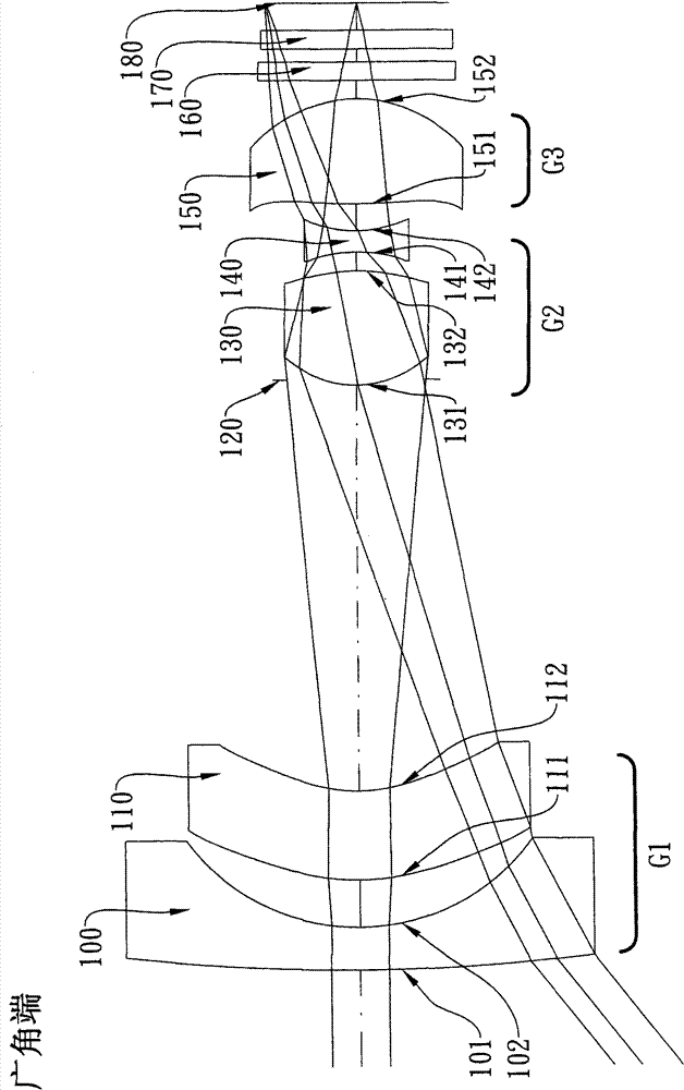
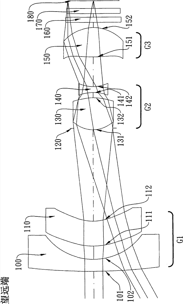
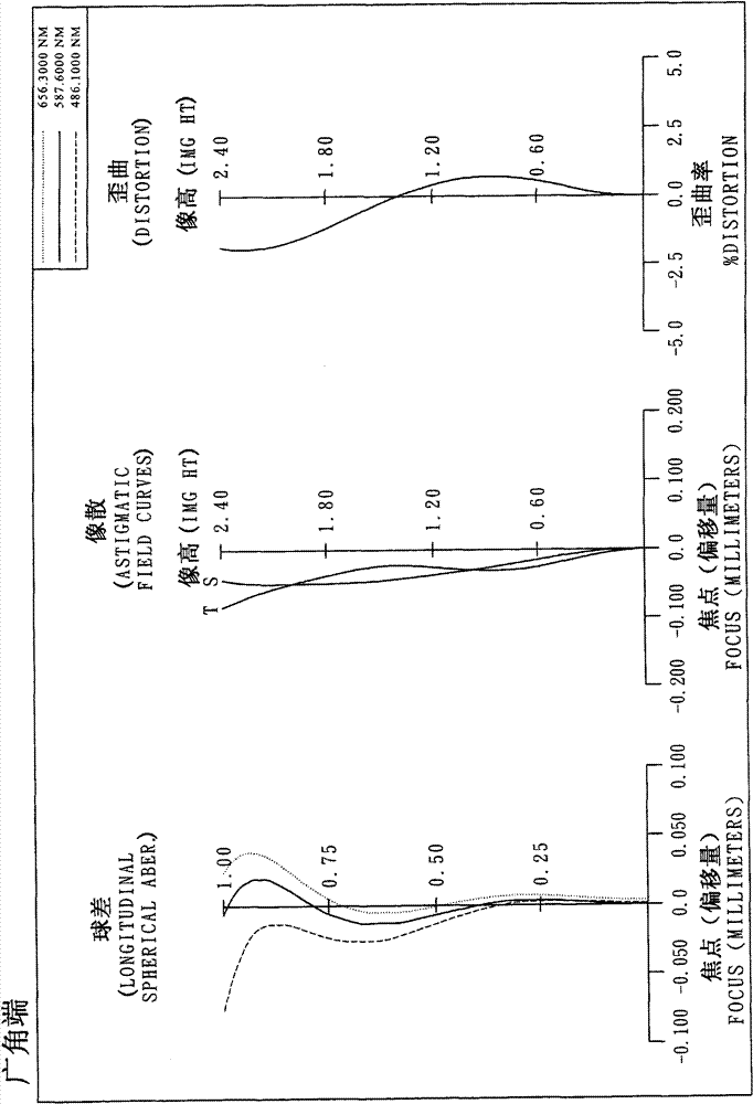
[0079] Please refer to Figure 1 A and Figure 1 B for the schematic diagram of the optical system of the first embodiment of the present invention operating at the wide-angle end and the telephoto end. For the aberration curves of the first embodiment operating at the wide-angle end and telephoto end, please refer to the second Figure A and the second Figure B. The variable focal length imaging lens of the first embodiment is mainly composed of three groups of mirrors, which are sequentially included from the object side to the image side: a first group G1 with negative refractive power, and a second group with positive refractive power The lens group G2 and a third lens group G3 with positive refractive power move on the optical axis through the second group lens group G2 to achieve zooming between the wide-angle end and the telephoto end, wherein:

[0080] There are only two lenses with refractive power in the first lens group G1, which include in sequence from the object sid...

no. 2 example 》

[0113] Please refer to Figure 3 A and Figure 3 B for the schematic diagram of the optical system of the second embodiment of the present invention operating at the wide-angle end and the telephoto end, and please refer to Figure 4 for the aberration curves of the second embodiment operating at the wide-angle end and telephoto end Figure A and the fourth Figure B. The variable focal length imaging lens of the second embodiment is mainly composed of three groups of mirrors, which are sequentially included from the object side to the image side: a first group G1 with negative refractive power, and a second group with positive refractive power The lens group G2 and a third lens group G3 with positive refractive power move on the optical axis through the second group lens group G2 to achieve zooming between the wide-angle end and the telephoto end, wherein:

[0114] There are only two lenses with refractive power in the first lens group G1, which include in sequence from the object...


PUM


Abstract

The invention discloses an imaging lens with a variable focus distance. The imaging lens with the variable focus distance comprises a first lens group with negative refracting power, a second lens group with positive refracting power, and a third lens group with positive refracting power from the object side to the image side in turn, wherein only two lenses in the first lens group have the refracting power; the first lens group comprises a first lens with negative refracting power and a second lens with negative refracting power from the object side to the image side in turn; the second lensgroup comprises an aperture, a third lens and a fourth lens from the object side to the image side in turn; the third lens group comprises a fifth lens; and the number of the lenses with the refracting power in the imaging lens with the variable focus distance is N which accords with the following relational expression: N is more than or equal to 5 and less than or equal to 7, and the lenses withthe refracting power in the imaging lens with the variable focus distance comprise at least three non-spherical lenses.

Description

technical field [0001] The invention relates to a variable focal length imaging lens, in particular to a miniaturized variable focal length imaging lens applied to portable electronic products. Background technique [0002] In recent years, with the rise of portable electronic products with photographic functions, the demand for miniaturized photographic lenses has increased day by day, and the photosensitive element of general photographic lenses is nothing more than a charge coupled device (CCD) or complementary There are two types of Complementary Metal-Oxide Semiconductor Sensor (CMOS Sensor), and with the advancement of semiconductor manufacturing technology, the pixel size of the photosensitive element is reduced, and the miniaturized photographic lens is gradually developing towards the high-pixel field. Therefore, The requirements for image quality are also increasing. [0003] Commonly seen miniaturized photographic lenses are mostly single-focus designs, and the m...

Claims


Application Information

Patent Timeline
Patent Type & Authority Patents(China)
IPC IPC(8): G02B15/177G02B13/18
Inventor 汤相岐蔡宗翰
Owner LARGAN PRECISION
Why Eureka
Try Eureka