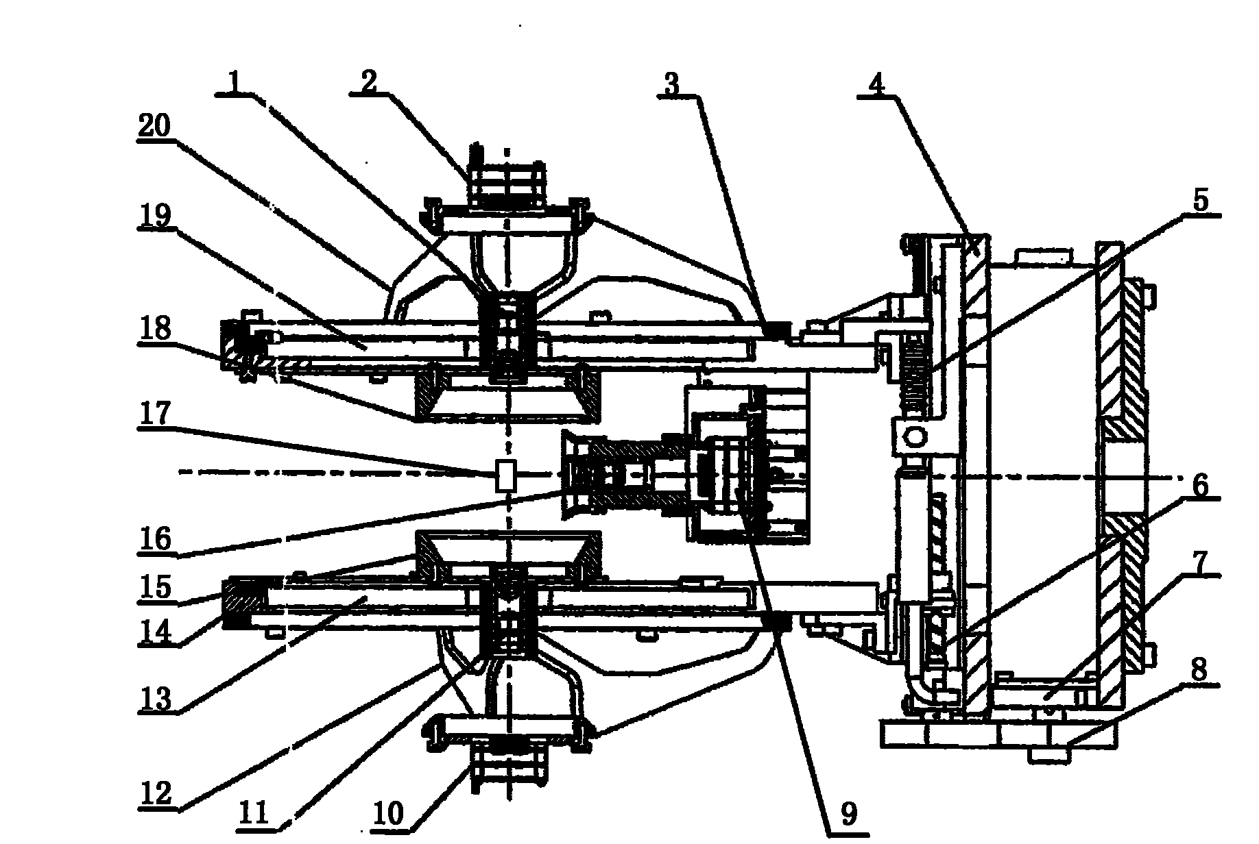
Moveable reflector laser collimator, moveable reflector target surface sensor and laser collimating method thereof
A technology of laser aiming and mirrors, which is applied in optics, instruments, telescopes, etc., can solve problems such as the inability to accurately obtain spatial information such as the angle of laser incidence, the balance of accuracy and efficiency of target surface sensors, and the inability to optimize laser energy distribution. Achieve the effects of solving multi-target feedback image aliasing, saving aiming time, and solving spot aliasing
- Summary
- Abstract
- Description
- Claims
- Application Information
AI Technical Summary
Problems solved by technology
Method used
Image
Examples
no. 1 approach
[0048] The structure and principle of the moving mirror laser sighting device of the present invention are described below.
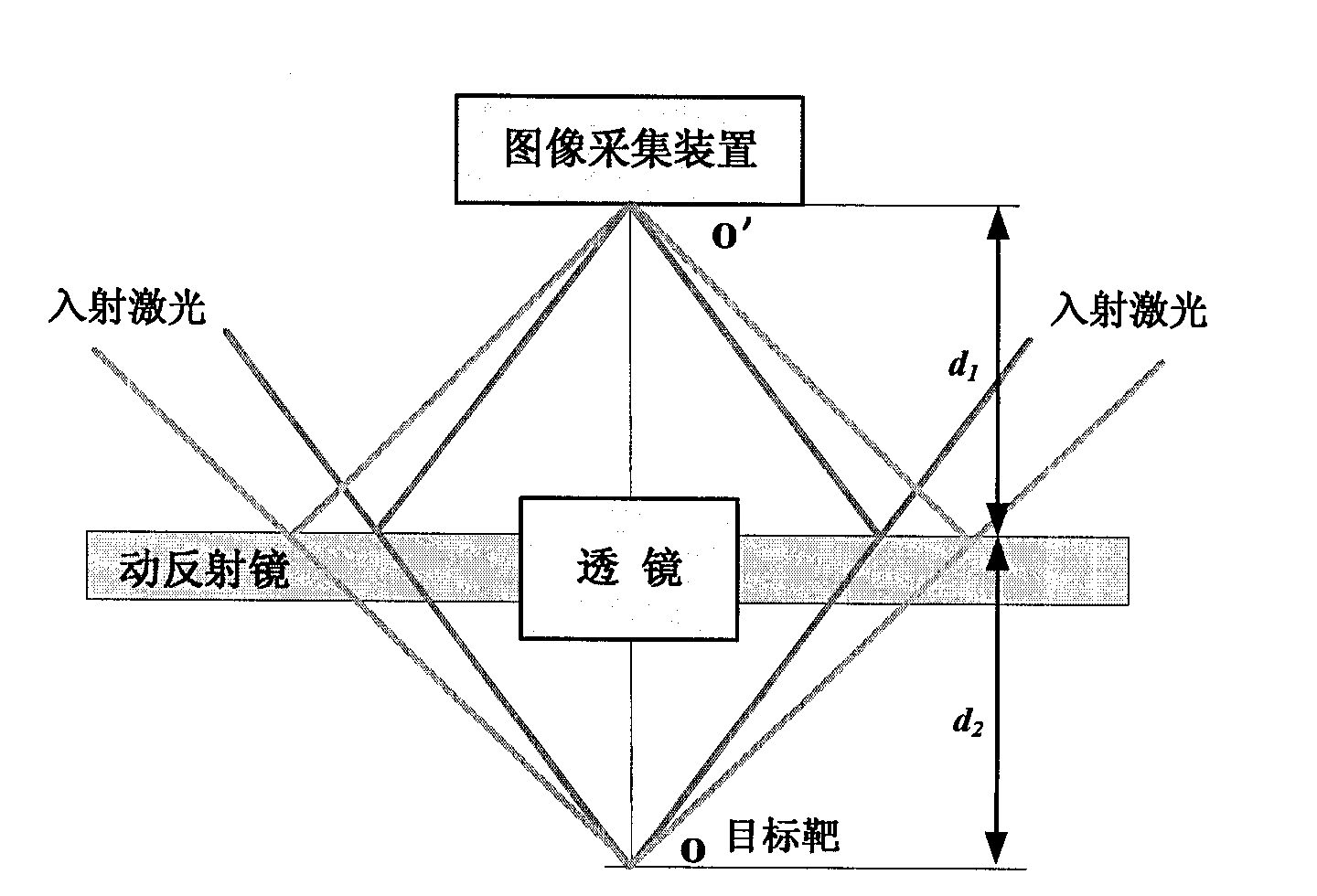
[0049] figure 2 It shows a schematic structural diagram of a laser sighting device with a moving mirror according to the first embodiment of the present invention.
[0050] Such as figure 2 As shown, the moving mirror laser sighting device includes a target O, multiple laser beams emitted by multiple lasers irradiate the target target, the image acquisition device is used to collect the light incident on it to form an image, and the lens is set at Between the target and the image acquisition device, the image of the target is transmitted to the image acquisition device. In particular, it also includes a moving mirror, which is arranged between the target and the image acquisition device, and reflects multiple laser beams emitted by the multiple lasers onto the image acquisition device to form a light spot, and The moving mirror can move linearly relative ...
no. 2 approach
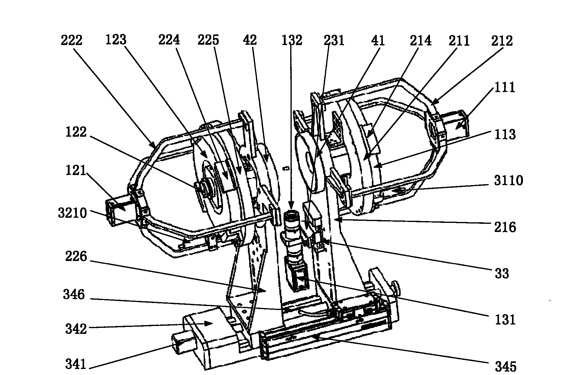
[0057] The following describes the moving mirror target surface sensor of the present invention. image 3 It is a schematic diagram of the three-dimensional structure of the moving mirror target surface sensor of the present invention. Figure 4 It is a front view of the structure of the moving mirror target surface sensor of the present invention. Figure 5 It is the left side view of the structure of the moving mirror target surface sensor of the present invention.
[0058] Such as image 3 , Figure 4 , Figure 5 As shown, the moving mirror target surface sensor of the present invention includes a first laser aiming device (located on the left in the figure), a second laser aiming device (located on the right in the figure), a central vision detection system, a differential focusing system, and Moving mirror servo drive system. Wherein, the first laser aiming device and the second laser aiming device both adopt laser aiming devices with the same structure and are arranged symme...
no. 3 approach
[0090] The working principle of the moving mirror laser sighting device of the present invention is described below.
[0091]
[0092] Figure 8 It is a schematic diagram of the relationship between the movement of the moving mirror and the track of the reflected laser spot.
[0093] Such as Figure 8 As shown, the laser is incident from point ①, reflected by the mirror, and imaged on the CCD. The imaging result on the CCD is displayed in a plan view above the CCD. When the mirror moves in the vertical arrow direction (that is, toward the CCD direction), its imaging point on the CCD moves in the horizontal arrow direction (on the CCD image sensitive surface). Specifically, when the mirror is in the conjugate position, the incident laser is reflected at point ②, and a spot is formed at point ② on the CCD image-sensitive surface; when the mirror moves to the CCD direction to position I, the incident laser is reflected at point ③ , And form a light spot at point ③ on the CCD image-se...
PUM
 Abstract
Description
Claims
Application Information
 - R&D
- Intellectual Property
- Life Sciences
- Materials
- Tech Scout
- Unparalleled Data Quality
- Higher Quality Content
- 60% Fewer Hallucinations
Browse by: Latest US Patents, China's latest patents, Technical Efficacy Thesaurus, Application Domain, Technology Topic, Popular Technical Reports.
© 2025 PatSnap. All rights reserved.Legal|Privacy policy|Modern Slavery Act Transparency Statement|Sitemap|About US| Contact US: help@patsnap.com


