Heat treatment apparatus and method of manufacturing semiconductor device
A heat treatment device, side technology, applied in semiconductor/solid-state device manufacturing, electrical components, circuits, etc., can solve problems such as leakage of gas, inability to implement process regulations, incomplete sealing, etc., to achieve high safety effects
- Summary
- Abstract
- Description
- Claims
- Application Information
AI Technical Summary
Problems solved by technology
Method used
Image
Examples
Embodiment 1
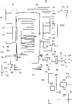
[0103] Using the heat treatment apparatus of the above-mentioned embodiment, the exhaust velocity of the exhaust device 301 was kept constant, and the temperature around the contact portion between the reaction tube 42 and the manifold 44 was measured under the following processing conditions in which the temperature of the processing chamber 201 was changed. of heat effects. As a result, the following temperature measurement results were obtained.
[0104] Processing conditions: the temperature in the processing chamber 201 (substrate processing temperature) is 1000° C., the set frequency of the exhaust device 301 (blower) is 30 Hz,
[0105] The measured value of the temperature around the contact portion between the reaction tube 42 and the manifold 44 is 124°C,
[0106] Processing conditions: the temperature in the processing chamber 201 (substrate processing temperature) is 1100° C., the set frequency of the exhaust device 301 (blower) is 30 Hz,
[0107] The measured val...
Embodiment 2
[0114] Using the heat treatment apparatus of the above-mentioned embodiment, the temperature of the treatment chamber 201 was kept constant, and the temperature around the contact portion between the reaction tube 42 and the manifold 44 was measured under the following treatment conditions in which the exhaust velocity of the exhaust device 301 was changed. heat-affected conditions. The following temperature measurement results were obtained.
[0115] 1) Processing conditions: the temperature in the processing chamber 201 (substrate processing temperature) is 1250° C., the set frequency of the exhaust device 301 (blower) is 20 Hz,
[0116] The measured temperature value around the contact portion between the reaction tube 42 and the manifold 44 is 237°C,
[0117] Processing conditions: the temperature in the processing chamber 201 (substrate processing temperature) is 1250° C., the set frequency of the exhaust device 301 (blower) is 30 Hz,
[0118] Measured temperature value...
Embodiment 3
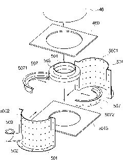
[0123] Using the heat treatment apparatus of the above-described embodiment, the temperature of the processing chamber 201 was kept constant, and the center of the gap 506 between the reaction tube 42 and the manifold 44 was measured under the following processing conditions in which the exhaust rate of the exhaust device 301 was changed. The surrounding height, that is, the thermal influence of multiple positions of the exhaust port 5021 in the circumferential direction of the reaction tube 42 . The following temperature measurement results were obtained.
[0124] 1) Processing conditions: the temperature in the processing chamber 201 (substrate processing temperature) is 1200° C., the set frequency of the exhaust device 301 (blower) is 20 Hz,
[0125] The measured temperature value at a position separated by about 90° from the exhaust port 5021 in the circumferential direction of the reaction tube 42, 450°C,
[0126] The measured temperature value at a position about 180° a...
PUM
 Abstract
Description
Claims
Application Information
 - R&D
- Intellectual Property
- Life Sciences
- Materials
- Tech Scout
- Unparalleled Data Quality
- Higher Quality Content
- 60% Fewer Hallucinations
Browse by: Latest US Patents, China's latest patents, Technical Efficacy Thesaurus, Application Domain, Technology Topic, Popular Technical Reports.
© 2025 PatSnap. All rights reserved.Legal|Privacy policy|Modern Slavery Act Transparency Statement|Sitemap|About US| Contact US: help@patsnap.com


