Line voltage compensation circuit based on peak detection current mode switch circuit
A technology of peak detection circuit and line voltage compensation, which is applied in the direction of conversion equipment without intermediate conversion to AC, can solve the problem that the peak current of the inductor cannot become a constant value, and overcome the instability of the peak current of the inductor and the constant peak current of the inductor. Change, reflect the effect of fast speed
- Summary
- Abstract
- Description
- Claims
- Application Information
AI Technical Summary
Problems solved by technology
Method used
Image

Examples
Embodiment Construction
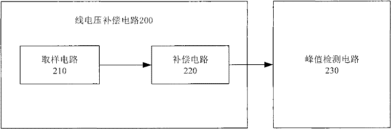
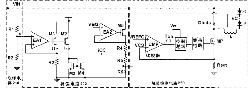
[0028] figure 2 It is a block diagram of the line voltage compensation circuit. The line voltage compensation circuit 200 includes a sampling circuit 210 and a compensation circuit 220 .
[0029] The sampling circuit 210 is used for sampling a voltage proportional to the line voltage VIN, so as to obtain a proportionally reduced sampling voltage that is linearly related to the line voltage VIN.
[0030] The compensation circuit 220 is connected to the sampling circuit 210, and is used to compensate the sampling voltage output by the sampling circuit 210 to the peak detection circuit 230 as an electrical signal, so that the inductor peak current is equal to the ideal inductor peak current IPK0. In one embodiment of the present invention, the compensation circuit 220 is used for converting the sampling voltage output by the sampling circuit 210 into a sampling current, and compensating the sampling current to the peak detection circuit 230 in the form of voltage. In another e...
PUM
 Abstract
Description
Claims
Application Information