Automatic gain adjustment circuit applied to burst transimpedance amplifier

An automatic gain adjustment, transimpedance amplifier technology, applied in the field of microelectronics, can solve problems such as the main pole shifting to the right, the loop is unstable, the quality of the output eye diagram is deteriorated, etc., to improve the safety and signal transmission quality, Good quality, loop stable results

Pending Publication Date: 2020-07-17
南京美辰微电子有限公司
View PDF0 Cites 2 Cited by
  • Summary
  • Abstract
  • Description
  • Claims
  • Application Information

AI Technical Summary

Problems solved by technology

When a large signal is input, the AGC circuit works, the transresistance becomes smaller, the dominant pole shifts to the right and becomes larger, the loop phase margin decreases, the loop is unstable, and the output eye diagram quality deteriorates

Method used


Image

  • Automatic gain adjustment circuit applied to burst transimpedance amplifier
  • Automatic gain adjustment circuit applied to burst transimpedance amplifier
  • Automatic gain adjustment circuit applied to burst transimpedance amplifier

Examples


Embodiment Construction

[0026] According to the attached Figure 1-6 The specific implementation manner of this technology is further explained:

[0027] This embodiment provides an automatic gain adjustment circuit applied to a burst transimpedance amplifier, including an automatic gain adjustment loop, a threshold generation circuit and a control voltage generation circuit, the threshold generation circuit is connected to the control voltage generation circuit, and the control voltage generation circuit is connected to the control voltage generation circuit. Automatic gain adjustment loop connection.

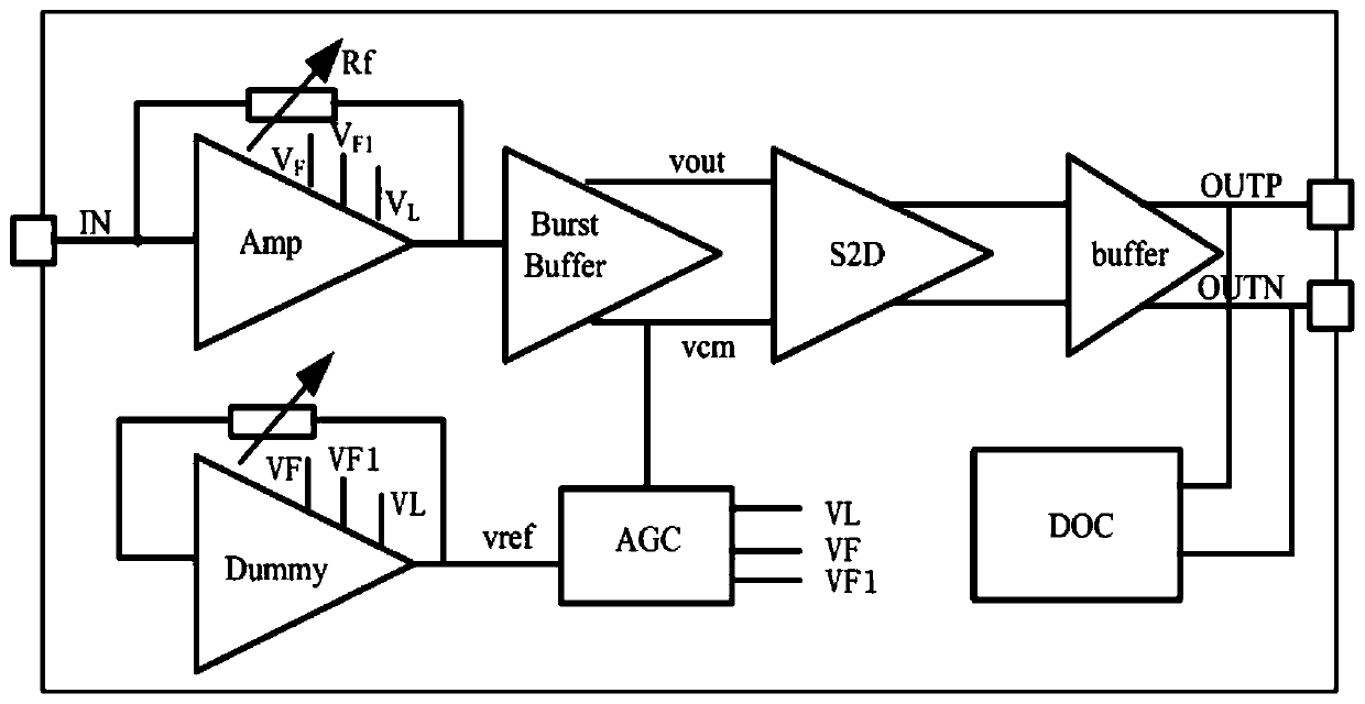
[0028] The block diagram of the burst transimpedance amplifier is as follows: figure 1As shown, the main chain consists of core amplifier Amp, burst buffer (burst buffer), single-ended to differential amplifier (S2D), output buffer (buffer), automatic gain control (AGC), differential mode offset cancellation (DOC) composition. The current signal is input from the IN terminal, converted into a sing...


PUM


Abstract

The invention discloses an automatic gain adjustment circuit applied to a burst transimpedance amplifier, which comprises an automatic gain adjustment loop, a threshold generation circuit and a control voltage generation circuit, wherein the threshold generation circuit is connected with the control voltage generation circuit, and the control voltage generation circuit is connected with the automatic gain adjustment loop; the automatic gain adjustment loop comprises a core amplifier, a working current adjusting circuit, a parallel transimpedance adjusting circuit and a parallel resistance value adjusting circuit. The working current adjusting circuit, the parallel transimpedance adjusting circuit and the parallel resistance value adjusting circuit are all connected with the core amplifier,and the working current adjusting circuit, the parallel transimpedance adjusting circuit and the parallel resistance value adjusting circuit are all connected with the control voltage generation circuit. The automatic gain adjustment circuit can ensure that a transimpedance amplifier loop is stable in a large dynamic range of an input signal, and devices on a transmission link do not enter an abnormal working state, so that the safety of a chip and the signal transmission quality can be remarkably improved.

Description

technical field [0001] The technology relates to the technical field of microelectronics, in particular to an automatic gain adjustment circuit applied to a burst transimpedance amplifier. Background technique [0002] With the rapid development of the global broadband access market, the domestic 100M broadband has gradually become the standard configuration. The existing PON (Passive Optical Network) technical standards are in terms of bandwidth requirements, business support capabilities, access node equipment and supporting equipment. Performance improvement and other aspects face new upgrade requirements. The downlink of PON adopts the TDM broadcasting method, and the uplink adopts the time division multiple access method. This mode of operation also determines that the transceiver circuit in the downstream direction of the PON (including the transmitter at the OLT end and the receiver at the ONU end) works in continuous mode; while the transceiver circuit in the upstre...

Claims


Application Information

Patent Timeline
Patent Type & Authority Applications(China)
IPC IPC(8): H03G3/30
CPCH03G3/30
Inventor 张浩邓青施家鹏
Owner 南京美辰微电子有限公司
Why Eureka
Try Eureka