Electric push rod-controlled photovoltaic generating set for automatically tracking sun with double shafts
An automatic tracking, electric push rod technology, applied in the field of solar energy applications, to achieve the effect of improving power generation efficiency, less working time, and low power consumption
- Summary
- Abstract
- Description
- Claims
- Application Information
AI Technical Summary
Problems solved by technology
Method used
Image

Examples
Embodiment 1
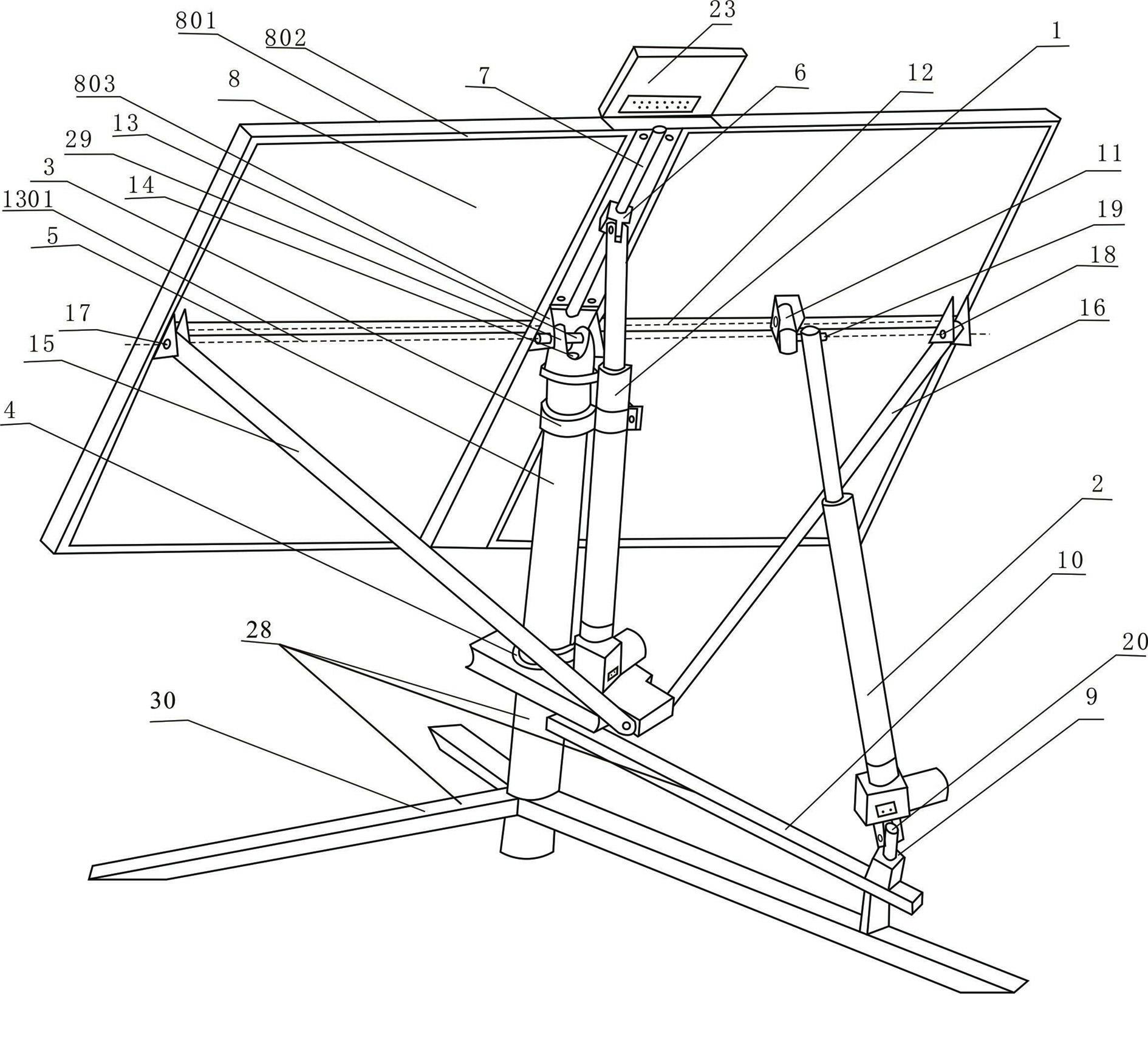
[0019] Example 1 as figure 1 Shown: a photovoltaic power generation device with two axes automatically tracking the sun controlled by an electric push rod, including a solar panel 8, a transmission mechanism for controlling the rotation of the solar panel, and it also includes a bracket 28, a connecting frame 29, a transverse shaft 13 and the longitudinal axis 14; the support 28 includes a base 30, a support column 5 and a crossbeam 10, the support column 5 is installed on the base 30, the crossbeam 10 is installed on the support column 5, and the connecting frame 29 is connected with the solar panel 8 through the transverse axis 13, and connected The lower part of the frame 29 is looped on the longitudinal axis 14, and the longitudinal axis 14 is fixed on the top of the support column 5; the transmission mechanism includes the height angle electric telescopic push rod 1 and the hour angle electric telescopic push rod 2; the lower bearing 4 is installed at the bottom of the sup...
Embodiment 2
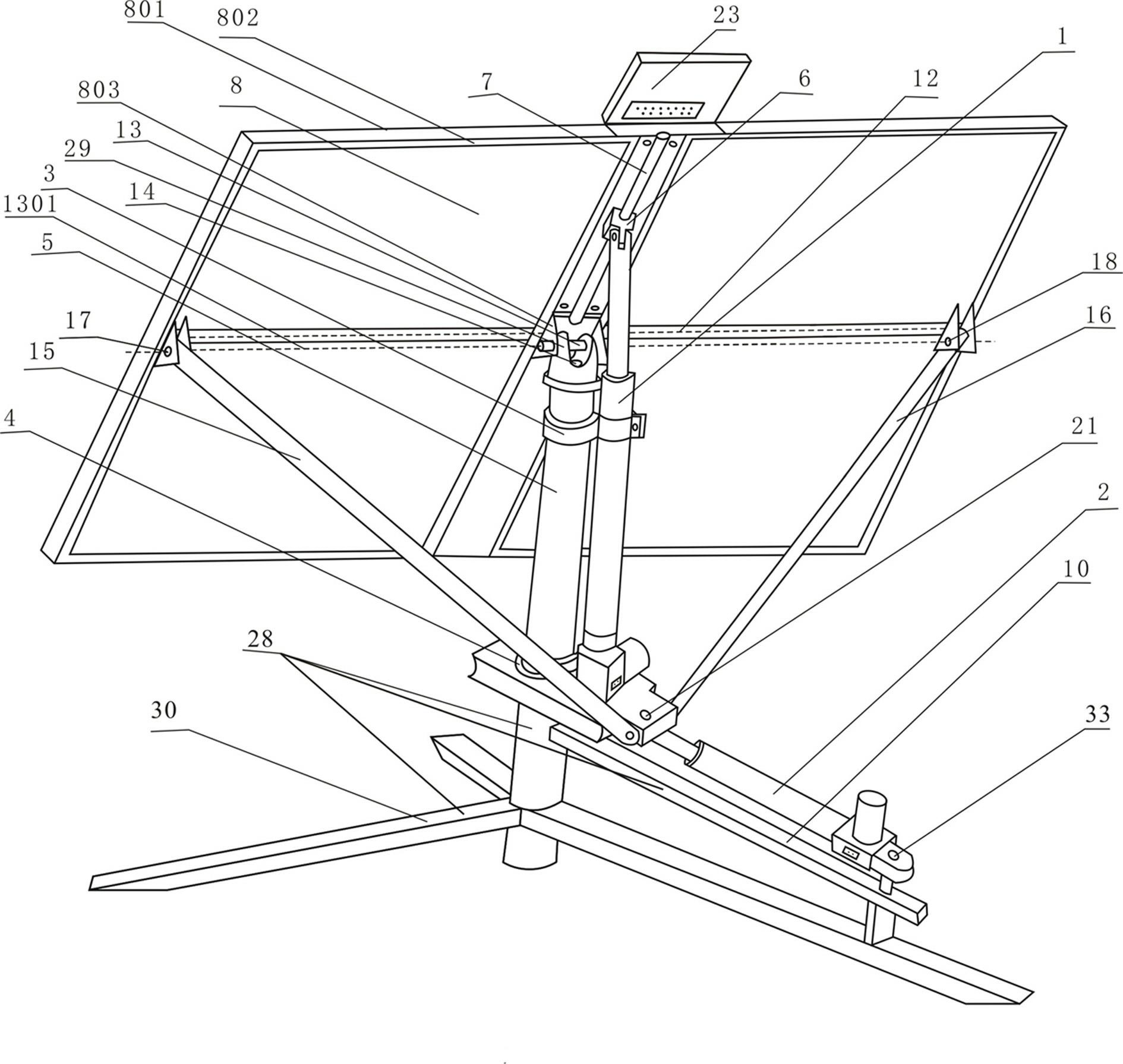
[0031] Example 2 figure 2 Shown is the second embodiment of the present invention, the crossbeam 10 is fixed with a vertical shaft 33, and one end of the hour angle electric telescopic push rod 2 is connected to the crossbeam 10 through the vertical shaft 33; the lower bearing 4 is equipped with a longitudinal shaft 21, and the hour angle The other end of the electric telescopic push rod 2 is connected with the longitudinal rotating shaft 21 . All the other structures are the same as in Example 1.
[0032] The hour angle electric telescopic push rod 2 telescopically pushes the lower bearing 4 to rotate, and drives the height angle electric telescopic push rod 1 fixed on the lower bearing 4 to rotate. Because the upper end of the height angle electric telescopic push rod 1 is connected to the solar panel 8, the solar panel is driven 8 rotates left and right, that is, it drives the solar panel 8 to rotate around the vertical axis 14 to track the solar hour angle.
Embodiment 3
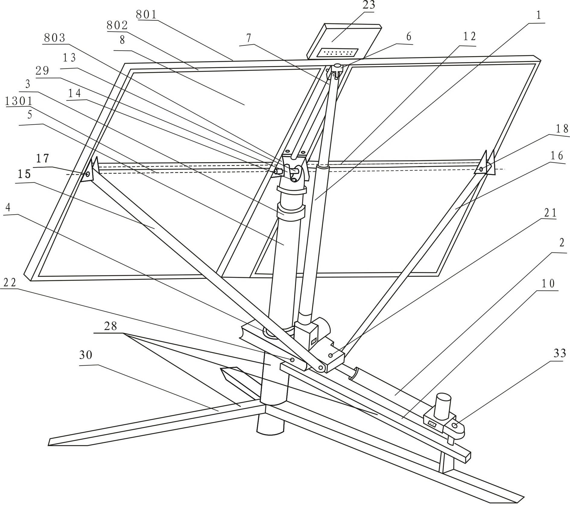
[0033] Example 3 image 3 Shown is the third embodiment of the present invention, the slider 6 is fixed on the upper end of the slide rod 7, the support column 5 is equipped with the upper bearing 3 and the lower bearing 4, the height angle electric telescopic push rod 1 is fixedly connected to the lower bearing 4, and the lower bearing 4 is fixed on the lower bearing 4. Bearing 4 is equipped with longitudinal rotating shaft 21 and horizontal rotating shaft 22, and crossbeam 10 is fixedly provided with vertical shaft 33, and one end of hour angle electric telescopic push rod 2 is connected to crossbeam 10 through vertical shaft 33, and the other end is connected with longitudinal rotating shaft 21; Telescopic push rod 1 is not associated with upper bearing 3. All the other structures are the same as in Example 1.
[0034] Since the upper bearing 3 has no constraints on the height-angle electric telescopic push rod 1, the connection between the lower end of the electric push r...
PUM
 Abstract
Description
Claims
Application Information
 - Generate Ideas
- Intellectual Property
- Life Sciences
- Materials
- Tech Scout
- Unparalleled Data Quality
- Higher Quality Content
- 60% Fewer Hallucinations
Browse by: Latest US Patents, China's latest patents, Technical Efficacy Thesaurus, Application Domain, Technology Topic, Popular Technical Reports.
© 2025 PatSnap. All rights reserved.Legal|Privacy policy|Modern Slavery Act Transparency Statement|Sitemap|About US| Contact US: help@patsnap.com