Forming section

A forming section and forming shoe technology, which is applied in the wet section of paper machines, textiles, papermaking, paper machines, etc., can solve the problems of high cost of negative pressure system and high energy consumption of negative pressure system operation, and achieve less splashing and excellent quality and intensity characteristics, flexible and variable effects

Active Publication Date: 2011-09-21
METSO PAPER INC
View PDF1 Cites 12 Cited by
  • Summary
  • Abstract
  • Description
  • Claims
  • Application Information

AI Technical Summary

Problems solved by technology

However, building a negative pressure system is expensive, and the

Method used


Image

  • Forming section
  • Forming section
  • Forming section

Examples


Example Embodiment

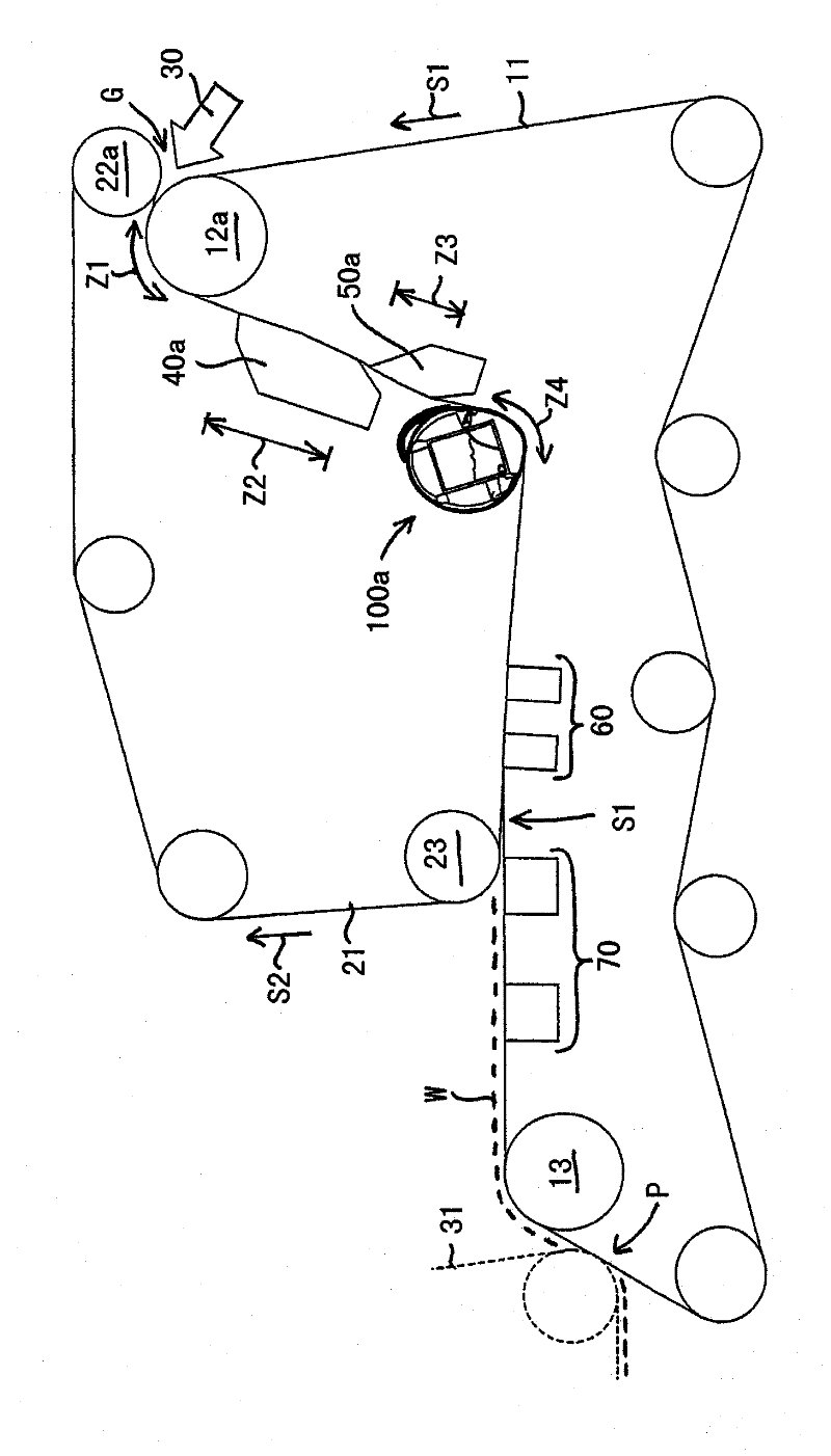
[0025] figure 1 A schematic side view of the forming part according to the present invention is shown.

[0026] The forming section includes a first wire loop 11 surrounding the forming roll 12a and a second wire loop 21 surrounding the first guide roll 22a. The traveling direction of the first net 11 is indicated by arrow S1, and the traveling direction of the second net 21 is indicated by arrow S2. The first mesh 11 and the second mesh 21 form a meeting gap G, so that the meshes 11 and 21 meet on the area of ​​the forming roll 12a. The headbox 30 supplies a jet of pulp suspension to this gap G between the nets 11 and 21. After passing through the meeting position, the nets 11, 21 travel in a specific portion on the outer surface of the forming roll 12a (the portion where the first dehydration zone Z1 formed by a curve is formed). After the first dewatering zone Z1 formed by the curve is a substantially straight double-wire part, the double-wire part has two dewatering zones Z...


PUM


Abstract

The forming section comprises two wire loops (11, 21) which form a twin- wire zone which comprises a dewatering element (40) performing initial dewatering and a dewatering device (100b) following it. The dewatering device (100b) comprises a stationary support shaft (110) on which are supported support elements (111, 112, 113, 114) around which circles an impermeable belt loop (120). The dewatering device (100b) further comprises a curvilinear dewatering zone (Z30) over which the wires (11, 21) travel supported by the belt loop (120). The degree of curvature of the curve of the curvilinear dewatering zone (Z30) increases in the travel direction of the belt (120) such that increasing dewatering pressure is applied to pulp suspension travelling between the wires (11, 21) on the curvilinear dewatering zone (Z30).

Description

technical field [0001] The invention relates to a forming section according to the preamble of claim 1 . Background technique [0002] In this specification, a fiber web machine means a paper machine, a board machine, a tissue machine and a pulp dryer. [0003] The function of the forming section is to remove water from the fiber suspension supplied by the headbox. The fiber suspension fed to the forming section typically has a consistency of 1% and the web formed on the forming section after passing through the forming section has a consistency of 18% to 20%. [0004] When the web is made from an aqueous lignocellulosic slurry, the water in the pulp is removed on the forming section by passing through one or more forming wires to initiate the forming of the web. The wood pulp fibers remain in a random distribution on the forming wire or between multiple forming wires moving together. [0005] Depending on the grade of web produced, different types of size are used. The ...

Claims


Application Information

Patent Timeline
IPC IPC(8): D21F1/48D21F9/00
CPCD21F7/005D21F9/003D21F1/36D21F1/48
Inventor 安蒂·波伊科莱宁
Owner METSO PAPER INC
Why Eureka
Try Eureka