
Plow

A technology of assembly and power output shaft, which is applied in the field of agricultural production and can solve the problems of high consumption and poor soil loosening effect.

Inactive Publication Date: 2011-09-28
吴小华
View PDF0 Cites 5 Cited by
  • Summary
  • Abstract
  • Description
  • Claims
  • Application Information

AI Technical Summary

Problems solved by technology

[0005] In order to solve the defects of poor soil loosening effect and high consumption in existing loosening methods, a plow machine is now provided, including a transmission and vibration assembly and a screw assembly

Method used


Image

  • Plow
  • Plow

Examples


Embodiment Construction

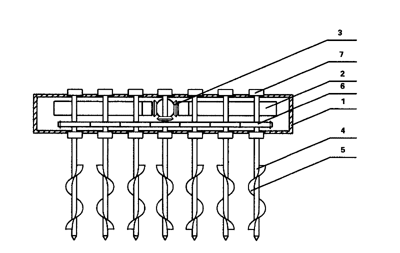
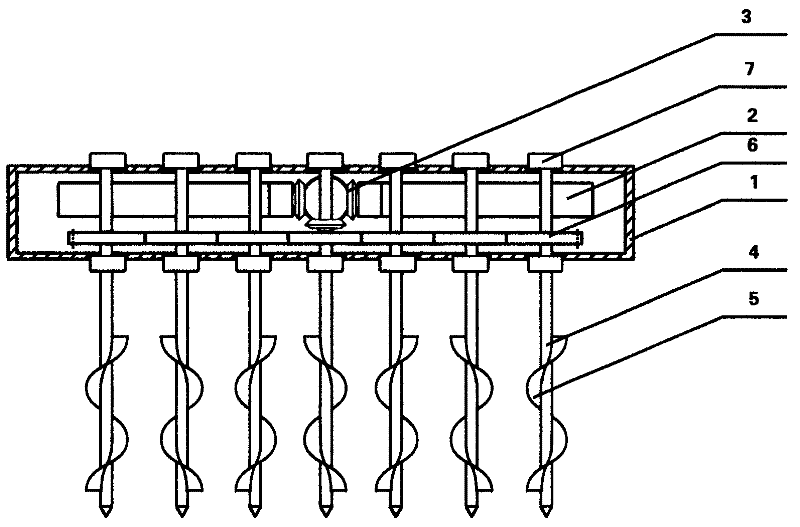
[0034] Such as figure 1 As shown, a plowing machine includes a transmission and vibration assembly and a screw body assembly.

[0035] As a preferred option.

[0036] The transmission and vibration assembly is provided with a power input shaft, the power input shaft is connected with the power output shaft and the vibrating part 2 through the transmission device of the gearbox 1, and the power output shaft is connected with the helix.

[0037] In order to ensure the transmission effect, it is the preferred solution.

[0038] The above-mentioned transmission device is a gear transmission device, and the power input shaft is connected with the power output shaft and the vibrating component 2 through a bevel gear 3 .

[0039] In order to improve the subsoiling effect, it is the preferred solution.

[0040] The above-mentioned spiral body assembly is composed of a screw rod 4 and a screw blade 5 .

[0041] In order to meet the agronomic requirements, it is the preferred soluti...


PUM


Abstract

The invention discloses a plow which relates to the field of agricultural production, in particular to a plow. The invention provides the plow to overcome the deficiencies of poor soil loosening effect and high consumption of the traditional soil loosening method. The plow comprises a driving / vibrating assembly and a spiral body assembly. The plow disclosed by the invention has a simple structure, is easy to popularize, and is suitable for production and application.

Description

technical field [0001] The invention relates to the field of agricultural production, in particular to a plow machine. Background technique [0002] The plow bottom layer generally exists in my country's cultivated land at a depth of 12 to 25 cm, and the thickness is about 8 to 15 cm. Due to the annual rolling by machines, the density and hardness of the plow bottom layer are much higher than that of the plow layer, which seriously hinders the root penetration of crops and the absorption of deep soil moisture and nutrients, directly affecting crop yield and quality. At the same time, due to the heavy use of land by farmers for many years, the excessive use of chemical fertilizers year after year in pursuit of production, and the neglect of the application of organic fertilizers have resulted in soil compaction, which has also affected the yield and quality of crops. [0003] The bottom layer of the plow can be broken through mechanical subsoiling and soil compaction can be ...

Claims


Application Information

Patent Timeline
IPC IPC(8): A01B33/00A01B33/08
Inventor 吴小华
Owner 吴小华
Learn More