
Steel grating plate press welder

A technology of steel grating and pressure welding machine, which is applied in welding equipment, resistance welding equipment, metal processing equipment, etc., can solve the problems of slow feeding speed, complex structure, poor precision, etc. The effect of high precision and simple structure

Inactive Publication Date: 2011-09-28
ZHAOYUAN QUANGANG MACHINERY
View PDF5 Cites 10 Cited by
  • Summary
  • Abstract
  • Description
  • Claims
  • Application Information

AI Technical Summary

Problems solved by technology

[0002] The steel grating is composed of load flat steel and cross bars perpendicular to the load flat steel, each arranged at a certain interval, and each intersection point of the load flat steel and the cross bar is welded and fixed by a pressure welding machine. At present, the production The countries of the steel grid plate pressure welding machine mainly include the United States, Japan, Australia and South Korea. The imported equipment has been imitated in China since 2000. The feeding mechanism of the steel grid plate pressure welding machine is a stepping trolley, and the feeding guide mechanism adopts a dovetail guide rail , The feeding and clamping mechanism adopts hydraulic clamping, which has defects such as large volume, complex structure, poor precision, and slow feed speed.

Method used


Image

  • Steel grating plate press welder
  • Steel grating plate press welder
  • Steel grating plate press welder

Examples


Embodiment Construction

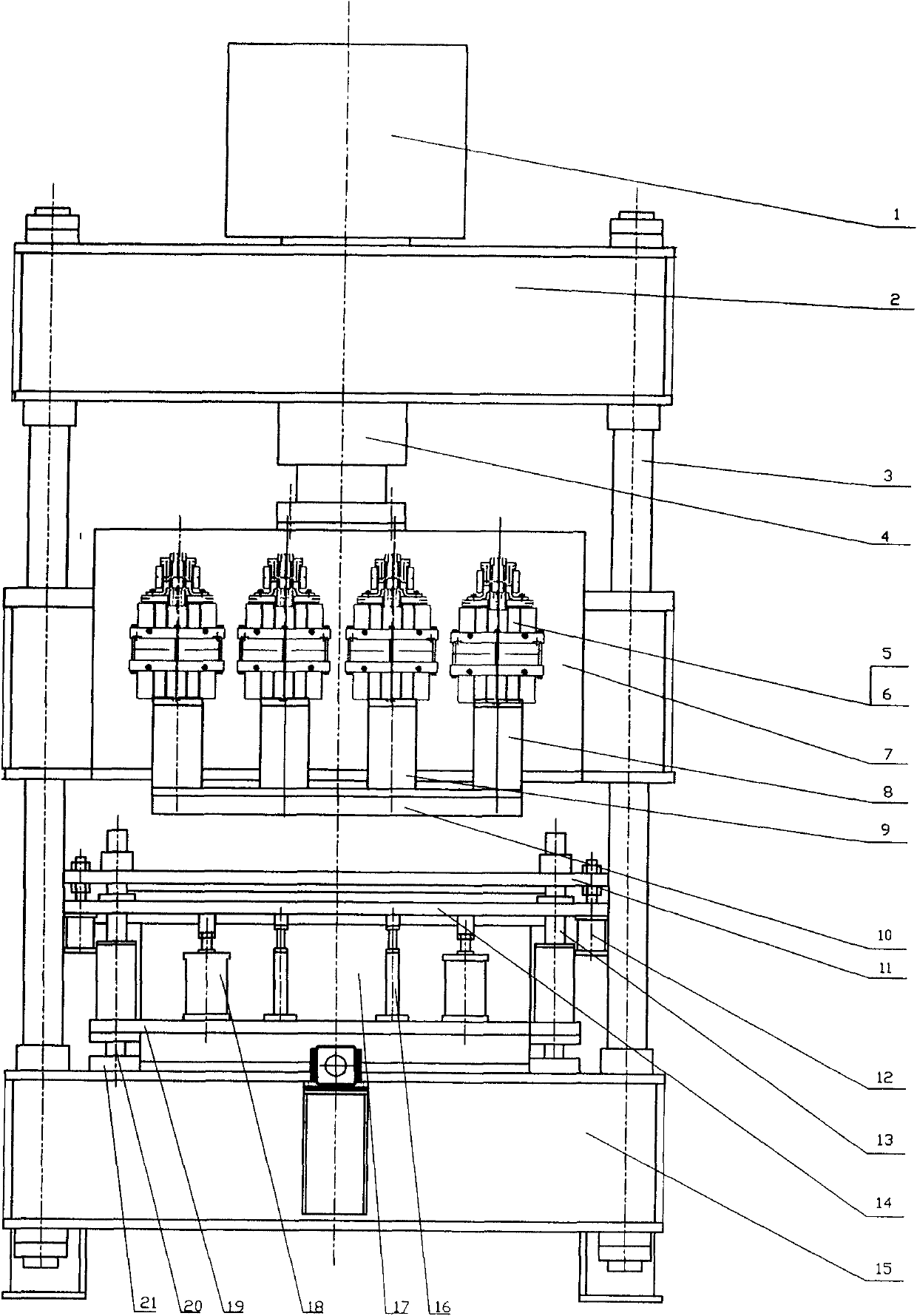
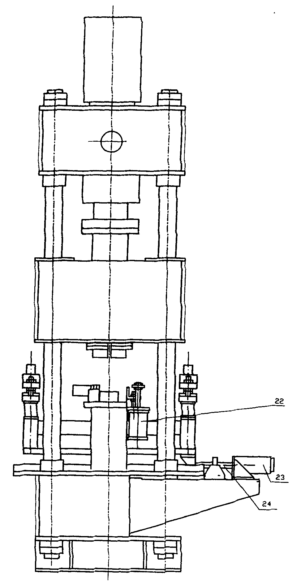
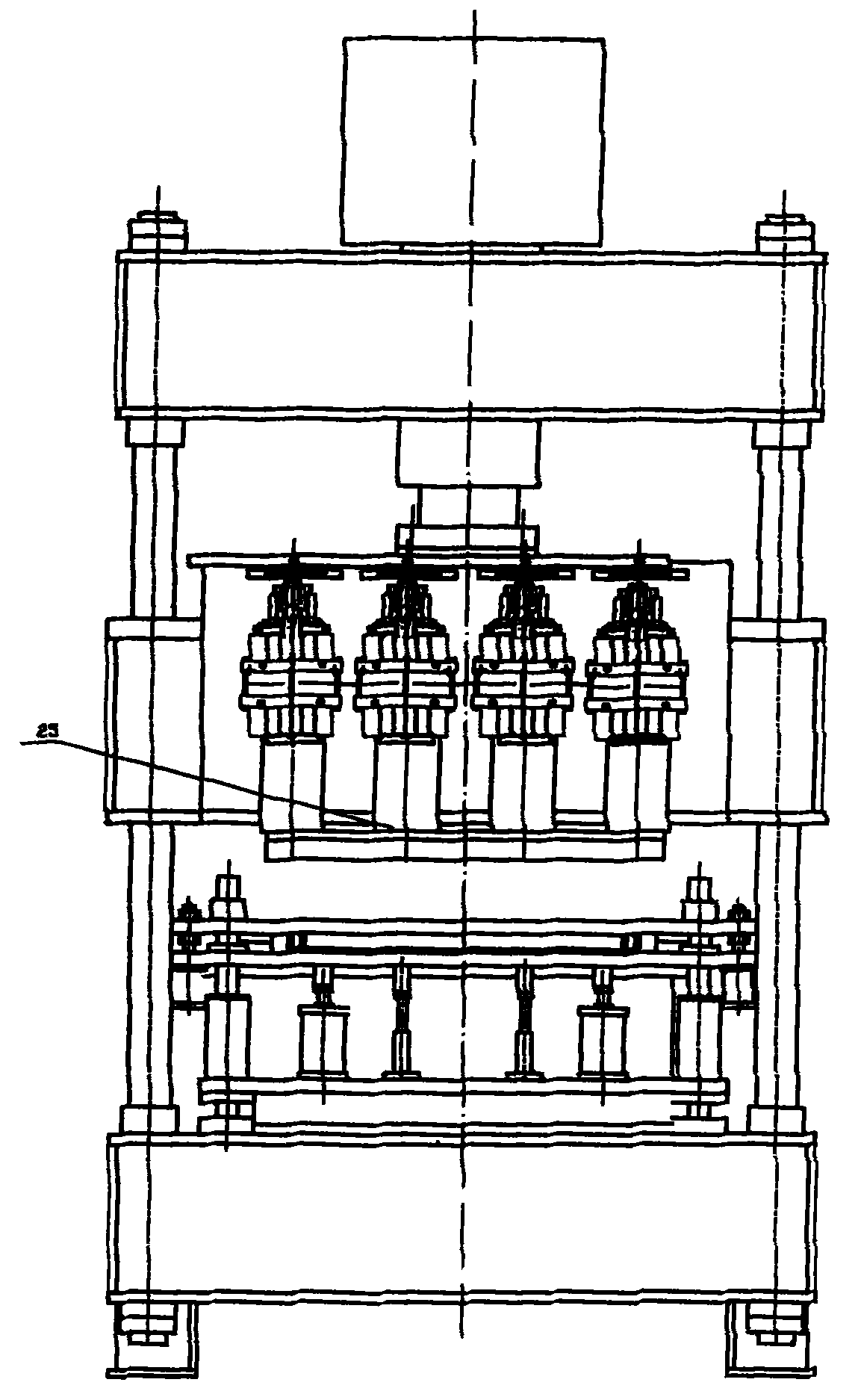
[0012] The front side of the lower beam 15 is connected to the servo motor 23, the output end of the servo motor 23 is connected to the ball screw 24, the upper end of the ball screw 24 is connected to the feeding frame 19, and the lower sides of the two ends of the feeding frame 19 are fixedly connected to the linear guide rail 20, and the linear guide rail 20 The lower end is connected to the linear guide rail base plate 21, the lower end of the linear guide rail base plate 21 is connected to the lower beam 15, the middle part of the upper end of the feeding frame 19 is connected to the lower clamping cylinder 18, and the two ends are connected to the guide post 13, the guide post 13 The upper end is connected to the lower clamping plate 14; at least three pairs of transformers 5 are connected to both sides of the middle of the slider 7, and each transformer 5 is connected to at least six diode rectifier assemblies 6, and the lower end of the transformer 5 is respectively conn...


PUM


Abstract

The invention discloses a steel grating plate press welder which comprises an oil tank (1), an upper cross beam (2), upright posts (3), a main oil cylinder (4), transformers (5), diode rectifying assemblies (6), slide blocks (7), an upper clamping plate (11), upper clamping cylinders (12), guide posts (13), a lower clamping plate (14), a lower cross beam (15), limiting plates (16), a bottom electrode (17), lower clamping plate cylinders (18), a servo motor (23), a ball screw (24) and a bottom electrode seat (26). The steel grating plate press welder is characterized in that: the upper end of the ball screw (24) is connected with a feeding frame (19); the lower sides at the two ends of the feeding frame (19) are connected with straight guide rail bottom plates (21) through straight guide rails (20); the lower ends of the straight guide rail bottom plates (21) are connected with the lower cross beam (15); the middle part at the upper end of the feeding frame (19) is connected with the lower clamping plate cylinder (18), and the two ends of the feeding frame (19) are connected with the guide posts (13); and the upper ends of the guide posts (13) are connected with the lower clamping plate (14). Therefore, the press welder is simple in structure, high in welding speed, high in feeding accuracy, convenient to use and particularly suitable for pressing steel grating plates.

Description

Technical field: [0001] The invention relates to a welding device, in particular to a steel grid plate pressure welding machine. Background technique: [0002] The steel grating is composed of load flat steel and cross bars perpendicular to the load flat steel, each arranged at a certain interval, and each intersection point of the load flat steel and the cross bar is welded and fixed by a pressure welding machine. At present, the production The countries of the steel grid plate pressure welding machine mainly include the United States, Japan, Australia and South Korea. The imported equipment has been imitated in China since 2000. The feeding mechanism of the steel grid plate pressure welding machine is a stepping trolley, and the feeding guide mechanism adopts a dovetail guide rail , The feeding and clamping mechanism adopts hydraulic clamping, which has defects such as large volume, complex structure, poor precision, and slow feed speed. Invention content: [0003] The ...

Claims


Application Information

Patent Timeline
IPC IPC(8): B23K11/36B23K11/02
Inventor 赵学涛邵东光战英峰
Owner ZHAOYUAN QUANGANG MACHINERY
Learn More