Active optical cable

An optical cable and cable technology, applied in the field of active optical cables, can solve the problems of restricting the performance of optical network systems, restricting user service bandwidth, and avoiding the use of copper wires, so as to achieve flexible and convenient access, improve service bandwidth, and avoid copper wires. effect used

Active Publication Date: 2011-09-28
SHENZHEN EPLU SCI TECH
View PDF4 Cites 4 Cited by
  • Summary
  • Abstract
  • Description
  • Claims
  • Application Information

AI Technical Summary

Problems solved by technology

[0007] (1) The product is too large and takes up user space
[0008] (2) May cause waste of resources
Most users only use one or several of these services, and other unused functions will cause waste
[0009] (3) High product cost
[0010] (4) Failure to completely avoid the use of copper wires
From the ONU to the user equipment, it is still necessary to use copper wires for signal transmission. Although this distance is limited, the use of copper wires in this last section has become the main bottleneck that limits the performance of the optical network system, which significantly restricts the user's service bandwidth.

Method used


Image

  • Active optical cable
  • Active optical cable
  • Active optical cable

Examples


Embodiment 1

[0041] Such as Figure 4 As shown, in the active optical cable of this embodiment, the optical transmission cable in the cable body adopts a dual optical fiber design, one of which is responsible for data reception (optical reception cable), and the other is responsible for data transmission (optical transmission cable) ), the end of the optical transmission cable connected to the optical connector is called the front end, and correspondingly, the other end (the end connected to the photoelectric conversion connector) is called the rear end. The optical connector at the front end is a dual-core optical fiber connector, which is mainly used to connect to the optical interface (the optical interface is located on the wiring panel, optical fiber panel, etc., for example), so as to access the optical network to obtain the optical signal from the OLT. ; The photoelectric conversion connector at the back end is mainly responsible for photoelectric conversion, from Figure 4 As can ...

Embodiment 2

[0047] Such as Figure 5 As shown, the active optical cable of this embodiment is exactly the same as the first embodiment in terms of the cable body, only the adapter is different: the first embodiment uses an adapter with a splitting function, which can distribute the AOC signal It is used for multiple user devices; and the second embodiment adopts the simplest one-to-one solution, that is, one AOC can only correspond to one entrance of the adapter. If users need to use multiple devices at the same time, they need to install routers or switches by themselves. . Or if there are multiple optical interfaces, AOCs can also be inserted into different optical interfaces, and each AOC can be inserted into different inlets of the adapter.

Embodiment 3

[0049] Such as Figure 6 As shown, in the active optical cable of this embodiment, its adapter has various interfaces, such as Figure 6 shows a WLAN interface, an RJ45 interface, an RJ11 interface, and an RF interface. Figure 6 Only one interface is shown for each of the above interfaces as an example. It can be understood that the types of interfaces are not limited to the above types, and the number of each type of interface is not limited to one. Due to the existence of multiple interfaces of the adapter, correspondingly, the signal processing chip needs to have the processing capability of multiple signals, and be able to control multiple signals such as voice, video, and Ethernet at the same time.


PUM


Abstract

The invention discloses an active optical cable which comprises a cable body, wherein the cable body comprises an optical transmission cable, an optical contactor and a photoelectric conversion contactor, wherein the optical contactor is connected with one end of the optical transmission cable, and the photoelectric conversion contactor is connected with the other end of the optical transmission cable and comprises a photoelectric conversion component and a signal processing chip. The active optical cable disclosed by the invention can be completely used as a finally-assessed copper wire in the current optical network system, so that a whole path between a local side and a user terminal is an optical path, and optical signals can be directly transmitted to the user terminal, therefore, the service bandwidth of a user can be greatly improved, and the performance of the optical network system can be played completely.

Description

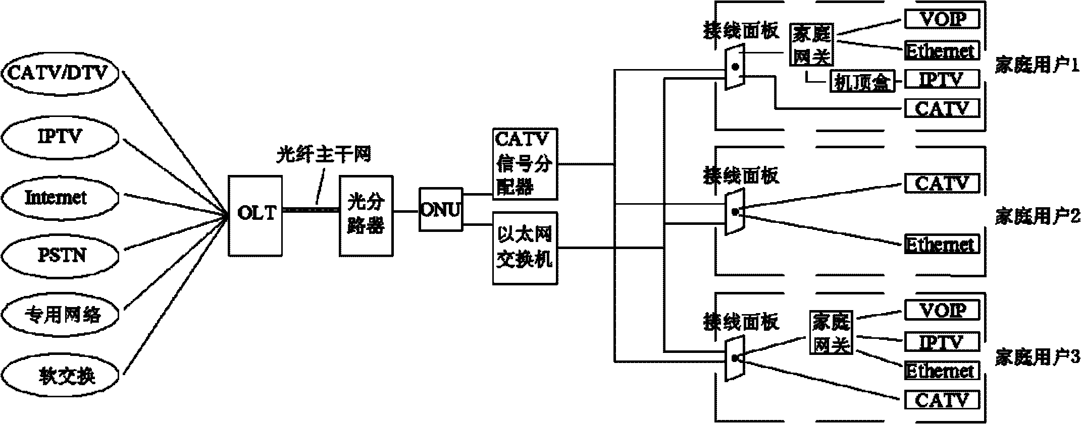
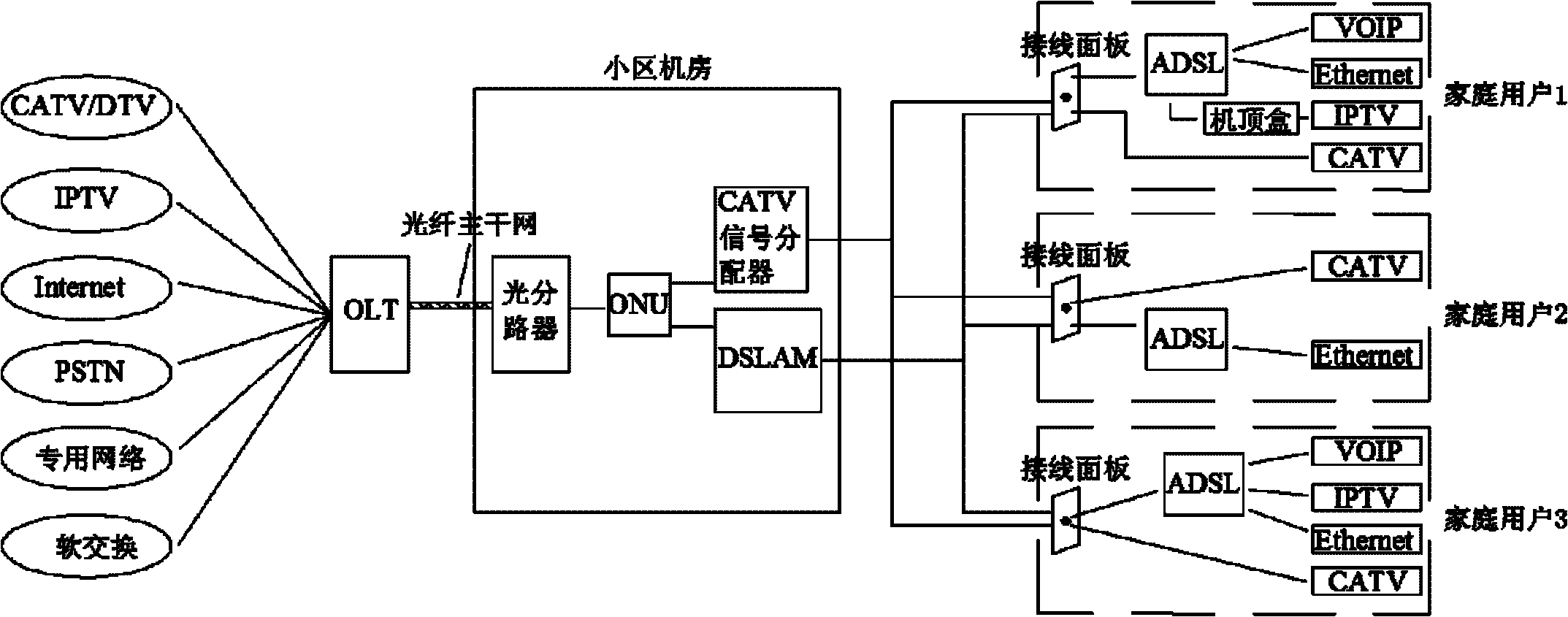
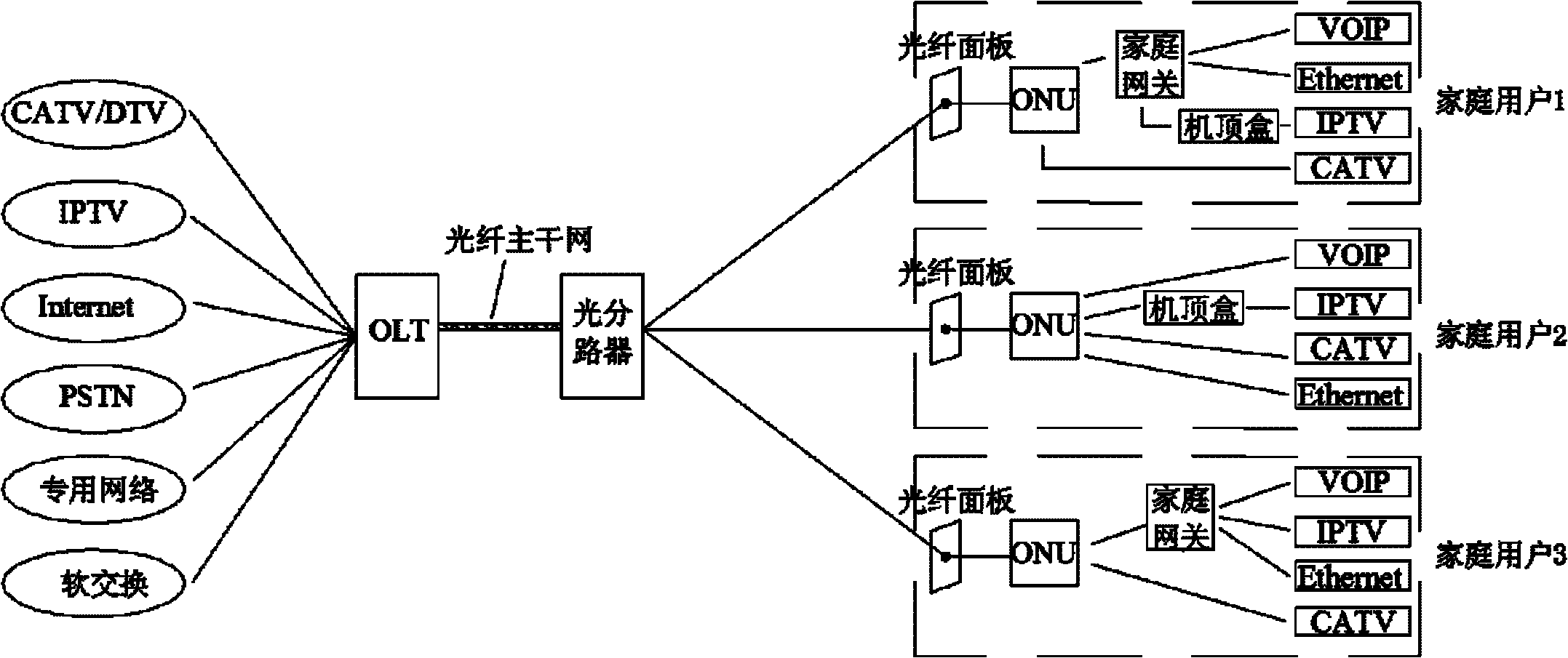
technical field [0001] The invention relates to optical transmission equipment, in particular to an active optical cable. Background technique [0002] A typical optical network system is mainly composed of OLT (Optical Line Terminal), ODN (Optical Distribution Network) and ONU (Optical Network Unit). The OLT is located at the central office and is the main control center to realize the function of network management; the ODN provides a transmission medium for the data connection between the OLT and the ONU, including optical cables and various optical components; the ONU is located at the user end and is used to connect into the user terminal. The following will briefly describe the principle of the existing EPON technology. [0003] figure 1 A network structure of FTTB (Fiber to The Building, fiber to the building) + LAN (Local Area Network, local area network) is shown. In the operator's computer room, various services are integrated into the OLT through related techn...

Claims


Application Information

Patent Timeline
Patent Type & Authority Applications(China)
IPC IPC(8): G02B6/44
Inventor 王文生王七月钟志云
Owner SHENZHEN EPLU SCI TECH
Why Eureka
Try Eureka