Orthogonal frequency division multiplexing passive optical network system

A passive optical network and orthogonal frequency division technology, applied in the field of communication, can solve problems such as the inability to realize the unified reception of multiple ONU unit data streams, the difficulty of implementing the upstream receiving module, and the complexity of MAC protocol control, etc., to achieve complex MAC control The effect of low density, flexible allocation mechanism, and low hardware cost

Inactive Publication Date: 2011-09-28
UNIV OF ELECTRONIC SCI & TECH OF CHINA
View PDF4 Cites 38 Cited by
  • Summary
  • Abstract
  • Description
  • Claims
  • Application Information

AI Technical Summary

Problems solved by technology

The upstream data stream after OFDM modulation is optically modulated on the separated optical carrier through the optical modulator, so as to realize upstream transmission, which greatly increases the difficulty of system design, and WDM-PON still lacks the flexibility to dynamically allocate the bandwidth between optical nodes
In addition, the uplink receiving module uses different detectors for different wavelengths, that is, if there are N ONUs in the PON system, N uplink receivers are required to make the hardware cost of the OLT end high. OLT, the optical splitter at the OLT end demultiplexes the signal at the receiving end and div

Method used


Image

  • Orthogonal frequency division multiplexing passive optical network system
  • Orthogonal frequency division multiplexing passive optical network system
  • Orthogonal frequency division multiplexing passive optical network system

Examples


Embodiment Construction

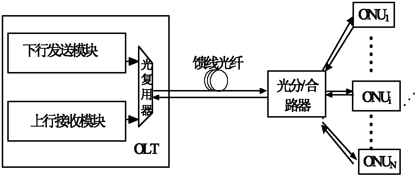
[0031] Downlink transmission means that the optical cable terminal equipment (OLT) in the CO (Central Office) sends information to multiple user-end optical nodes (ONU) through one or several 1:N passive optical splitter / combiners; Transmission refers to sending data from ONU to OLT. Only optical fiber and passive optical devices are used in the network between OLT and ONU.

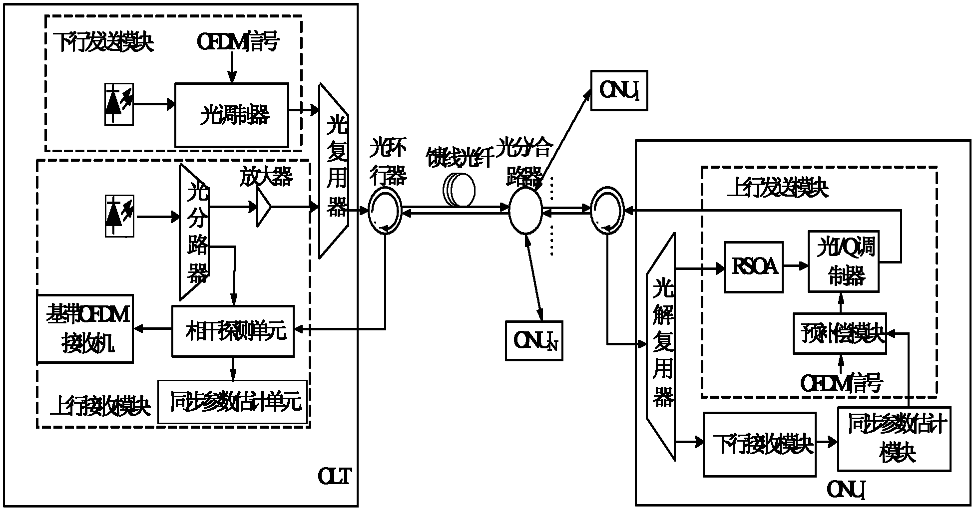
[0032] Such as figure 2 As shown, the total number of ONUs in the PON is N. The OLT includes a downlink sending module, an uplink receiving module, and an optical multiplexer; each ONU includes an optical demultiplexer, a downlink receiving module, an uplink sending module, and a synchronization parameter estimation module.

[0033] The downlink transmission module includes a downlink optical laser and an optical modulator; the downlink data modulated by OFDM flows through the optical modulator and then is transmitted to each ONU unit through the feeder fiber; the downlink optical laser provides an opt...


PUM


Abstract

The invention provides an orthogonal frequency division multiplexing passive optical network system, which modulates an uplink data stream by using orthogonal frequency division multiplexing (OFDM) on the basis of not increasing hardware cost and media access control (MAC) complexity. The system adopts OFDM modulation for both uplink transmission and downlink transmission. In the OFDM modulation of uplink data, the positions and bandwidths of frequency bands allocated to each optical network unit and used for bearing valid uplink data in the whole converged OFDM frequency band are variable. Different frequency bands are allocated to uplink channels of different optical nodes, so that the frequency bands allocated to all the ONUs in the system and used for bearing the valid uplink data are positioned at different positions of the whole OFDM frequency spectrum, and are not overlapped with one another. An uplink transmission module can perform adaptive source configuration, dynamically allocate the number of sub-carriers according to the traffic of a user and regulate the bandwidths of the frequency bands used for bearing the valid uplink data.

Description

technical field [0001] The invention relates to communication technology, in particular to passive optical network communication. Background technique [0002] In the next-generation passive optical network (Passive Optical Networks, PON), common time division multiplexing PON (TDM-PON) and wavelength division multiplexing PON (WDM-PON) systems. TDM-PON access requires complex time control algorithms and framing techniques to support different applications; WDM-PON systems still lack the flexibility to dynamically allocate bandwidth between optical nodes, which is necessary for future optical access networks of. With the development of Orthogonal Frequency Division Multiplexing (OFDM) technology, its high spectrum utilization rate and large dispersion tolerance make it a more effective modulation method. However, the current PON only adopts the OFDM modulation method in the downlink transmission of data, and still uses the conventional OOK (On-off Key, on-off keying) and D...

Claims


Application Information

Patent Timeline
IPC IPC(8): H04Q11/00H04L27/26
Inventor 易兴文张静张洪波邓明亮邱昆
Owner UNIV OF ELECTRONIC SCI & TECH OF CHINA
Why Eureka
Try Eureka