Pattern drawing mechanism for founding moulding and founding moulding machine using the pattern drawing mechanism

A technology of mold lifting mechanism and molding machine, which is applied in the direction of molding machines, casting molding equipment, manufacturing tools, etc., can solve the problems of large impact force of the overall molding machine, shorten the service life, and unevenness of up and down, so as to reduce labor intensity, Guarantee the precision of mold release and the effect of small impact

Inactive Publication Date: 2011-10-05
陆腾
View PDF6 Cites 6 Cited by
  • Summary
  • Abstract
  • Description
  • Claims
  • Application Information

AI Technical Summary

Problems solved by technology

Traditional compaction is achieved by manual beating, which is laborious and inefficient. Later, a mechanical compaction mechanism was introduced. Although the labor force was liberated, the compaction effect was not ideal. When compacting, it is generally compacted from top to bottom. Here There is a shortcoming that the upper molding sand is compacted, while the lower one is relatively loose. There is unevenness in the upper and lower parts, and the quality of the casting product is still difficult to guarantee. At the same time, mechanical compaction has a relatively large impact on the overall molding machine, which is easy to cause damaged, thereby reducing the useful life
In addition, in the traditional molding of the sand box, the transfer of the sand box requires manual operation, the labor intensity of the workers is high, and it is easy to damage the formed shape

Method used


Image

  • Pattern drawing mechanism for founding moulding and founding moulding machine using the pattern drawing mechanism
  • Pattern drawing mechanism for founding moulding and founding moulding machine using the pattern drawing mechanism
  • Pattern drawing mechanism for founding moulding and founding moulding machine using the pattern drawing mechanism

Examples


Embodiment Construction

[0039] The present invention will be further described in detail below in conjunction with the accompanying drawings and embodiments.

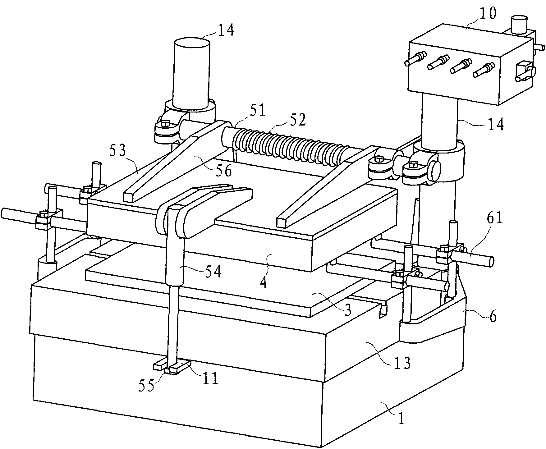
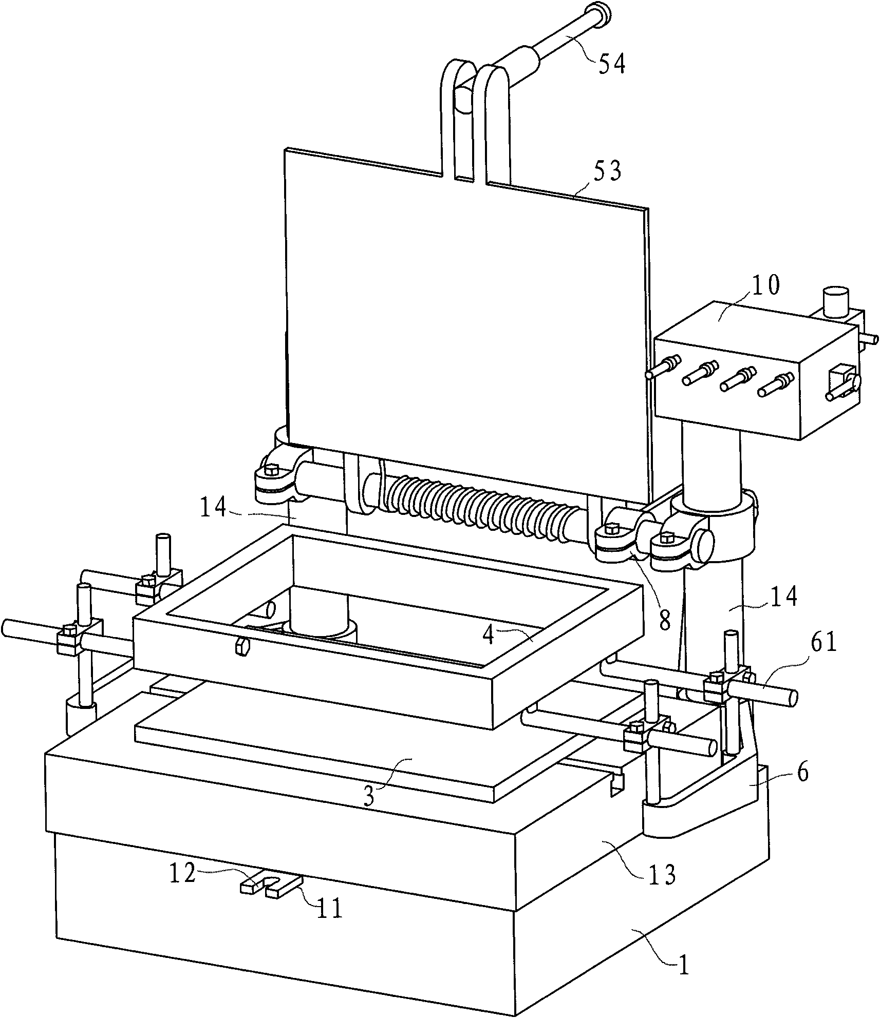
[0040] Such as figure 1 , figure 2 with image 3 As shown, the foundry molding machine in this embodiment includes a base 1 , a column 14 , a sand mold 3 , a sand box 4 , a mold lifting bracket, a platen mechanism and a control box 10 .

[0041] The base 1 is hollow to form an inner cavity, the inner cavity has a cylinder assembly 8, the upper port of the base 1 has a worktable 13 that can vibrate and lift under the action of the cylinder assembly 8, and the inner wall of the base 1 has an upper stopper 18 and a lower stopper 19 (see image 3 shown). There are two upright columns 14, which are arranged at the rear side of the base 1 at intervals in the longitudinal direction, and the sand mold 3 is located on the worktable 23 . The sand box 4 is arranged on the sand mold 3, and cooperates with the sand mold 3 to form a closed area for ac...


PUM


Abstract

A pattern drawing mechanism for founding moulding is characterized in that the mechanism comprises a pedestal, columns, a sand mould, a sandbox, and a pattern drawing bracket; a workbench plate is disposed at the upper end of the pedestal, the two columns are disposed at the back side part of the pedestal vertically with an interval; the pattern drawing bracket comprises two branch brackets facing to each other; each branch bracket is bended, and a central part is connected to the respective column and is rotatable; both front end parts have a support bar respectively, and back end parts are connected to a sliding member together; correspondingly, a guiding member is transversely extended out from the back end part of the pedestal; and the sliding member is disposed on the guiding member and is capable to move back and forth. The invention also discloses a founding moulding machine using the pattern drawing mechanism. Compared with the prior art, the pattern drawing mechanism of the invention has the advantages of convenient and fast operation, reduced labor intensity, no displacement or deformation of the sand mould, and can guarantee the precision of subsequent casting products.

Description

technical field [0001] The invention relates to a mold-lifting mechanism, and also relates to a foundry molding machine using the mold-lifting mechanism. Background technique [0002] Foundry casting is widely used in the casting of metal products. Firstly, a sand mold whose inner cavity matches the product is produced by a foundry molding machine, and then the heated molten metal is poured into the sand mold through the sprue. After cooling, it is solidified to obtain the obtained product. The required product, the molding sand is generally made of quartz sand with strong refractoriness. When the molding sand is molded into a sand mold, it needs to be compacted, so that the density of each part of the sand mold will be uniform, and the quality of the obtained casting product can be guaranteed. Traditional compaction is achieved by manual beating, which is laborious and inefficient. Later, a mechanical compaction mechanism was introduced. Although the labor force was liberat...

Claims


Application Information

Patent Timeline
Patent Type & Authority Applications(China)
IPC IPC(8): B22C15/34
Inventor 陆腾陆亚明
Owner 陆腾
Why Eureka
Try Eureka