Vertical type one-way combination valve for reciprocating type gas-liquid two-phase mixture conveying pump

A reciprocating, combined valve technology, applied in the direction of variable capacity pump components, pump components, liquid fuel engines, etc., can solve the problems of reducing the service life of the valve group, unfavorable gas phase medium discharge, small flow area, etc., to reduce pressure. Loss and waste of energy, improve overall operating performance, increase the effect of flow channel area

Inactive Publication Date: 2011-10-05
杭州佳湖科技有限公司
View PDF5 Cites 0 Cited by
  • Summary
  • Abstract
  • Description
  • Claims
  • Application Information

AI Technical Summary

Problems solved by technology

However, the existing combined valve has a small flow area, especially the area of ​​the inlet port and the valve inlet, which leads to a large flow rate of the medium in the valve body. When the medium enters the pump body, it will cause a large amount of energy loss and reduce the suction performance of the pump.
At the same time, the flow rate of the medium is too high, which causes the opening height of the valve ring and the valve plate to be too high, the closing lag angle increases, and the backflow of the medium increases accordingly, which reduces the volume coefficient of the pump, causes partial pressure loss of the medium, and wastes energy. The vibration and noise of the valve group increases during operation, which reduces the service life of the valve group
In addition, the traditional combination valve is set horizontally, which is not conducive to the discharge of the gaseous medium, resulting in failure to transport or even pump failure

Method used


Image

  • Vertical type one-way combination valve for reciprocating type gas-liquid two-phase mixture conveying pump
  • Vertical type one-way combination valve for reciprocating type gas-liquid two-phase mixture conveying pump
  • Vertical type one-way combination valve for reciprocating type gas-liquid two-phase mixture conveying pump

Examples


Embodiment 1

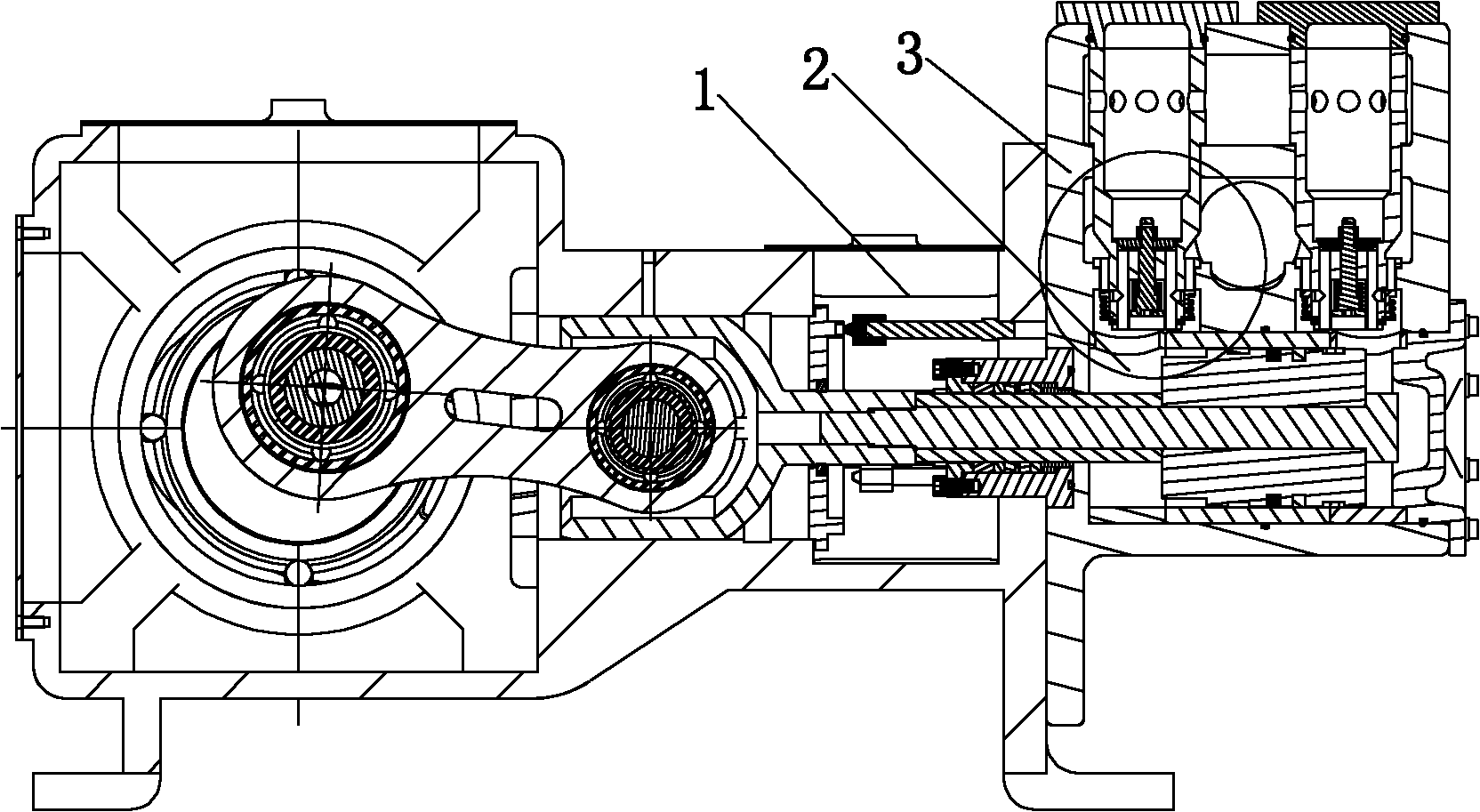
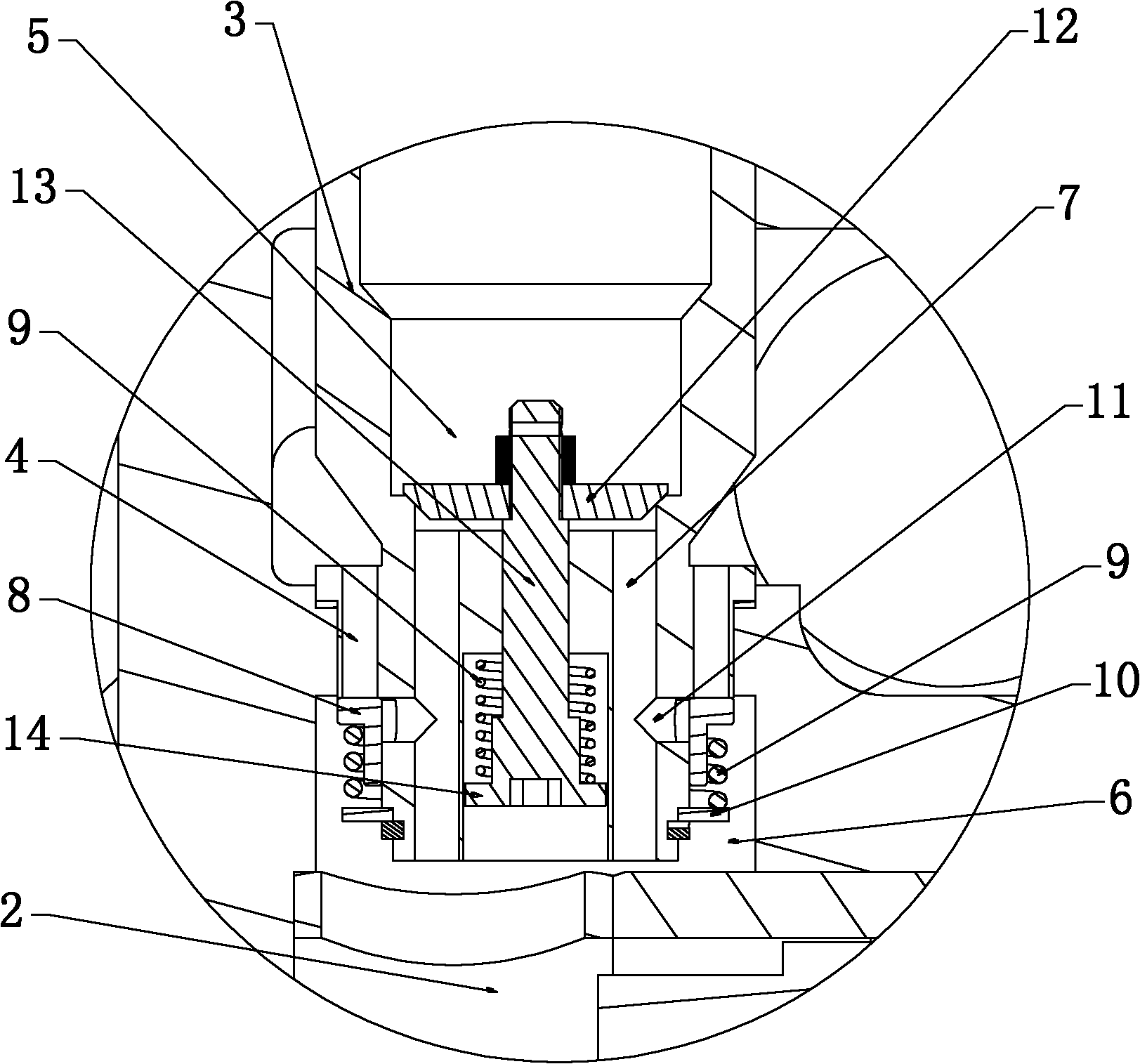
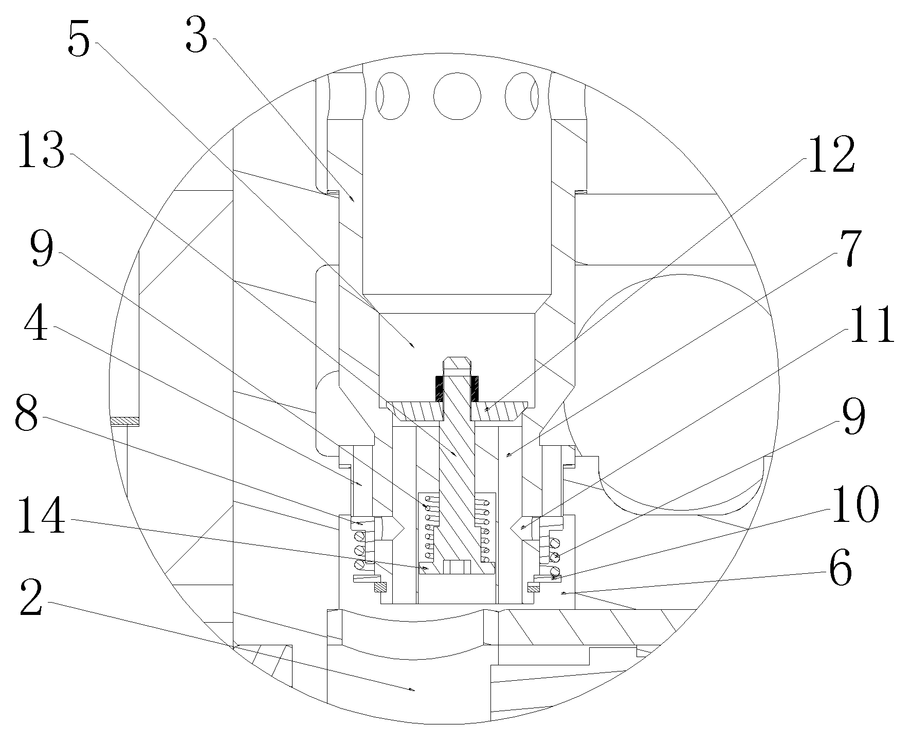
[0012] Such as figure 1 , figure 2 As shown, the vertical one-way combined valve for the reciprocating gas-liquid two-phase mixed delivery pump described in this embodiment mainly includes a valve body 3, a valve inlet 4, a valve outlet 5, an inlet chamber 6 and an outlet chamber 7. The valve body 3 is vertically arranged at the opening of the cavity 2 of the pump body 1, the valve outlet 5 is arranged on the inner ring of the valve body 3, the valve inlet 4 is arranged on the outer ring of the valve body 3, and a valve ring 8 is arranged in the inlet cavity 6 , a compression spring 9 is provided on the valve ring 8, and the compression spring 9 is limited by the stop ring 10 provided on the valve body 3, and a shunt hole 11 is provided on the valve body 3 between the inlet cavity 6 and the outlet cavity 7, The valve outlet 5 is provided with a valve plate 12, the valve plate 12 is connected with one end of the vertical rod 13, and one end of the vertical rod 13 in the outle...


PUM


Abstract

The invention provides a vertical type one-way combination valve for a reciprocating type gas-liquid two-phase mixture conveying pump, which mainly comprises a valve body, a valve inlet, a valve outlet, an inlet chamber and an outlet chamber, wherein the valve outlet is arranged at an inner ring of the valve body, the valve inlet is arranged at an outer ring of the valve body, a valve ring is arranged in the inlet chamber, a through hole is arranged in the valve body between the inlet chamber and the outlet chamber, and the valve outlet is provided with a valve plate. In the vertical type one-way combination valve for the reciprocating type gas-liquid two-phase mixture conveying pump, as the valve outlet is arranged at the inner ring of the valve body, and the valve inlet is arranged at the outer ring of the valve body, the flow path area of the valve inlet is increased, and the flow rate of a medium at the valve inlet is decreased, so that energy waste can be reduced, and the suction performance of the pump can be improved; and meanwhile, as a flow dividing hole is arranged in the valve body between the inlet chamber and the outlet chamber, a double-flow path structure is realized, and the flow rate of the medium at the valve inlet is further decreased, so that the opening height of the valve ring can be reduced, a lag angle of closing the valve ring can be reduced, and the pressure loss and the energy waste can be reduced.

Description

technical field [0001] The invention relates to a combined valve for a reciprocating pump, in particular to a vertical one-way combined valve for a reciprocating gas-liquid two-phase mixed delivery pump. Background technique [0002] Reciprocating pumps are an indispensable type of product in industrial pumps, and their performance does not change with changes in discharge pressure and viscosity of the conveying medium. Its working chamber is isolated from the outside world by a sealing device, and the volume of the working chamber is periodically changed by the reciprocating movement of the piston in the liquid cylinder. The pump valve (suction valve, discharge valve) is connected with the pipeline or closed to absorb and discharge the medium. It is a very important fluid machine. The suction valve and discharge valve used are special valve groups for reciprocating pumps. However, the existing combined valve has a small flow area, especially the area of ​​the inlet port a...

Claims


Application Information

Patent Timeline
Patent Type & Authority Applications(China)
IPC IPC(8): F04B53/10
Inventor 张鹤周深彪
Owner 杭州佳湖科技有限公司
Why Eureka
Try Eureka