Roof natural-ventilation deduster

A technology of natural ventilation and dust collector, applied in chemical instruments and methods, solid separation, separating solids from solids with airflow, etc., can solve the problem of shortening the service life of factory buildings, destroying the production and living environment of human beings, and affecting the production efficiency of enterprises and other issues, to achieve the effect of high social value, low maintenance cost and high cost performance

Active Publication Date: 2013-06-12
锦州鹏翔电力轻钢设备有限公司
View PDF0 Cites 0 Cited by
  • Summary
  • Abstract
  • Description
  • Claims
  • Application Information

AI Technical Summary

Problems solved by technology

A large amount of dust accumulated on the roof for a long time is not only inconvenient to clean, but also increases the load on the roof and shortens the service life of the factory roof; the dust falling to the land and farmland causes serious pollution of air, water and soil, and destroys the production and living environment of human beings. , a threat to human health
At the same time, each region has strict indicators for industrial dust emissions. Excessive dust emissions limit production and affect the production efficiency of enterprises.

Method used


Image

  • Roof natural-ventilation deduster
  • Roof natural-ventilation deduster
  • Roof natural-ventilation deduster

Examples


Embodiment 1

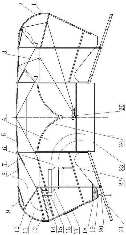
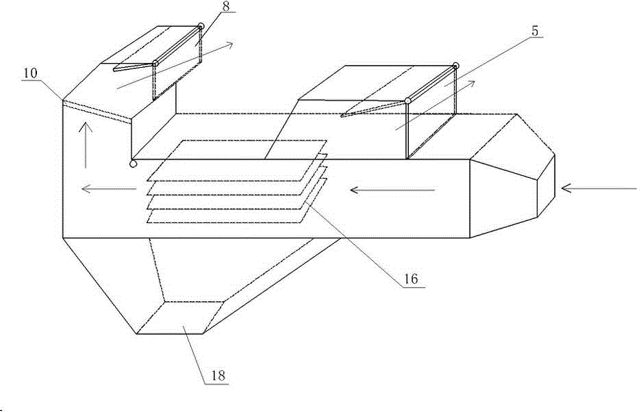
[0027] like Figure 1 ~ Figure 4 As shown, the roof natural ventilation deduster includes roof supports 1, and the roof supports 1 are in multiple groups, and one group is arranged at intervals of 3 to 3.5 meters along the longitudinal direction of the roof. An outer guard plate 2 is provided on both sides and ends of the roof support 1, a sloping floor 22 is provided at the bottom of the roof support 1, a ventilation outlet 5 is provided on the top of the roof support 1, and a roof vent is provided at the bottom of the roof support 1 23. An electric switch mechanism 25 is provided on the roof bracket 1, and the electric switch mechanism 25 adopts a wire rope traction machine (an electric linkage mechanism can also be used). The position adjacent to the outside of the ventilation outlet 5 on the roof bracket 1 is provided with a dust removal outlet 8, and the ventilation outlet 5 and the dust removal outlet 8 on the top of the roof bracket 1 corresponding to the two sides of t...

Embodiment 2

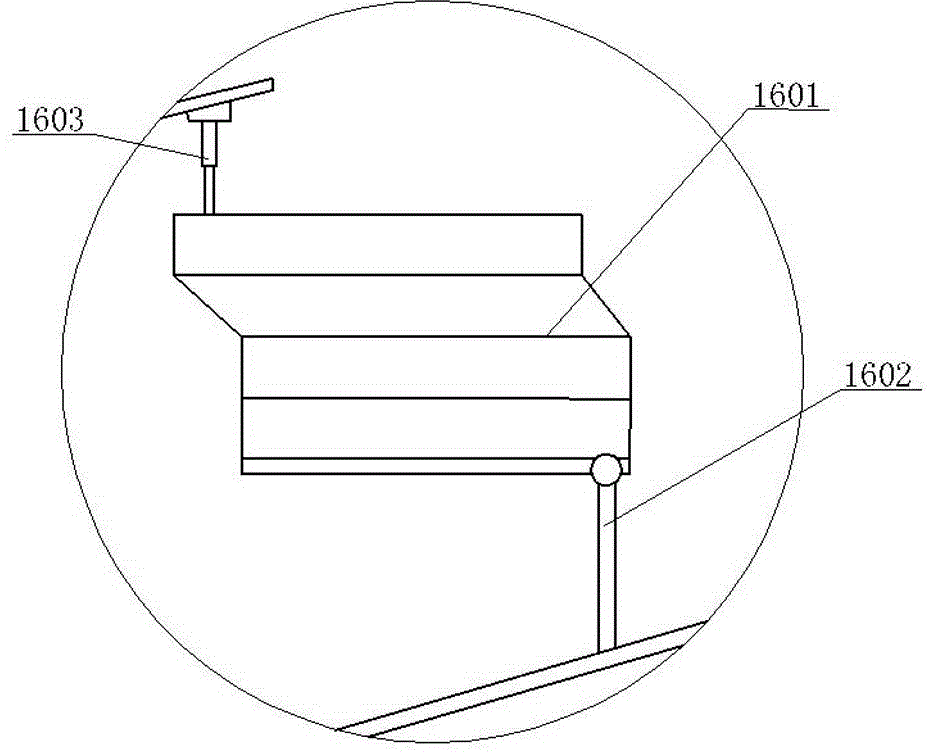
[0031] like Figure 5As shown, a drainage hole 13 communicating with the drainage groove 12 is provided at the position corresponding to the drainage groove 12 on the outer guard plate 2, so that the accumulated water flowing through the drainage groove 12 is directly drawn out from the drainage hole 13, and when rain or snow occurs Sometimes the rain and snow falling on the rain shield 3 are discharged through the drainage hole 13 with the drainage groove 12 and do not fall into the dust collection groove 18, so as to facilitate the recovery and reuse of dust.


PUM


Abstract

The invention relates to a roof natural-ventilation deduster comprising a roof bracket, an outer guard plate, an inclined bottom plate, a ventilating exhaust outlet, a roofing ventilation opening and an electric switch mechanism, wherein a dedusting exhaust outlet is arranged on the adjacent position of the roof bracket and the ventilating exhaust outlet; a rainproof plate is arranged on a position of the upper part of the roof bracket, which corresponds to the ventilating exhaust outlet and the dedusting exhaust outlet; a ventilating regulation valve plate and a dedusting regulation valve plate are arranged at the ventilating exhaust outlet and the dedusting exhaust outlet; a flow guide plate is arranged on the roof bracket; a flow guide region, a horizontal through-flow dilation region and a back-turning dedusting region are arranged between the roofing ventilation opening and the flow guide plate, between the rainproof plate of the dedusting exhaust outlet and the outer guard plateand between the dedusting exhaust outlet and the horizontal through-flow dilation region respectively; a turnover multilayer dedusting partition plate is arranged in the horizontal through-flow dilation region; a water discharge groove is arranged between the rainproof plate and the outer guard plate; and a dust collection groove is arranged between the outer guard plate and the inclined bottom plate. The invention has the advantages of simple structure, convenience for installation, good ventilating effect, high dedusting efficiency, low energy consumption, energy saving and environment friendliness without noises.

Description

technical field [0001] The invention relates to the field of industrial dust removal, in particular to a roof natural ventilation dust collector. Background technique [0002] The closed roof ventilator is a device that uses the naturally formed air pressure to raise and discharge the air in the building. It has good ventilation performance and complete wind shelter ability, and is widely used in industrial buildings. Although existing roof ventilators have good ventilation performance, they cannot solve the dust removal problem. Although there are many purification and dust removal devices in the production workshops of some factories, they cannot be used or the ideal dust removal effect is not achieved due to the limitation of the production process requirements, so that a large amount of harmful industrial dust is discharged along the roof ventilator. Part of the discharged industrial dust falls on the roof of the workshop, and the other part falls to the farmland with t...

Claims


Application Information

Patent Timeline
Patent Type & Authority Patents(China)
IPC IPC(8): B07B9/00
Inventor 单连勤单嘉恒单连勇
Owner 锦州鹏翔电力轻钢设备有限公司
Why Eureka
Try Eureka