
Upper deburring machine for continuous casting slab

A technology of deburring machine and slab, applied in the field of continuous casting slab deburring machine, can solve the problems of difficult to master surfacing welding technology, low blade service life, and reduced adhesion between the blade and the surface of the billet, etc., which is beneficial to equipment maintenance and security. Product performance, the effect that is conducive to product maintenance

Active Publication Date: 2011-10-12
唐山市润捷机械设备制造有限公司
View PDF6 Cites 13 Cited by
  • Summary
  • Abstract
  • Description
  • Claims
  • Application Information

AI Technical Summary

Problems solved by technology

[0003] One is the hammer-knife deburring machine. Due to structural reasons, the hammer-knife deburring machine cannot be applied to slabs with wider width and thinner thickness, so its scope of application is narrow;
[0004] The other is a disc-blade deburring machine with a single row of cutter bars. The drive of the cutter bar is driven by an air source. Due to the poor operating environment of the deburring machine (the temperature of the billet is as high as 700 ° C, and the use of air cooling can not be well Cool down the blade and the knife rod, and there is dust in the environment), which leads to the poor sealing of the cylinder sleeve of the knife rod lifting, so that the knife rod cannot rise to the working position due to air leakage in the cylinder, or although the knife rod rises to the working position, but due to Cylinder air leakage reduces the adhesion between the blade and the surface of the billet, causing the blade to retract when the blade encounters hard burrs and the deburring effect cannot be achieved
The disc blades used in the deburring machine are all processed by surface surfacing technology. Because the surfacing technology is difficult to master, the service life of the blades is relatively low, and the average replacement cycle is about 2 months, which directly results in the maintenance cost of the deburring machine. high status

Method used


Image

  • Upper deburring machine for continuous casting slab
  • Upper deburring machine for continuous casting slab
  • Upper deburring machine for continuous casting slab

Examples

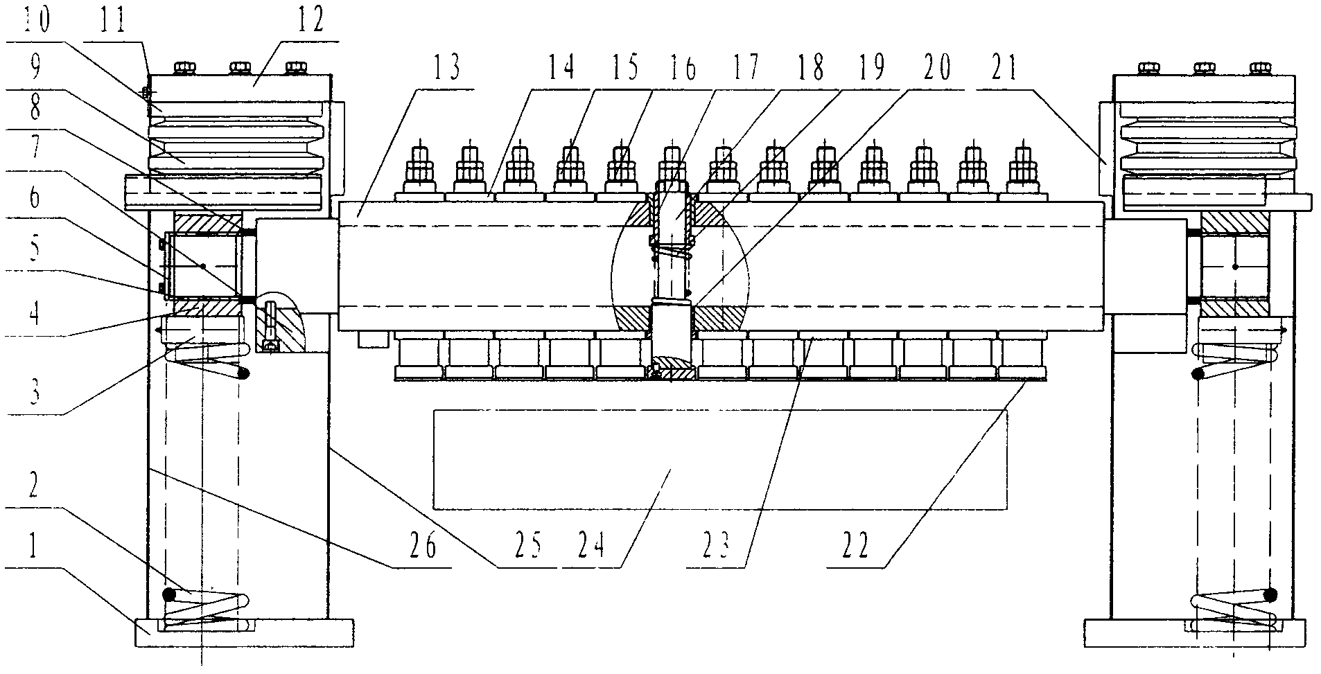

Embodiment Construction

[0023] The deburring machine is a special equipment for removing the steel slag on the gas cutting edge of the steel billet on the steelmaking production line.

[0024] 1. The current status of the deburring machine:

[0025] At present, all steel mills do not deal with the burrs on the upper surface of the slab, but as the rolling mills have higher and higher requirements on the quality of the slab, it is increasingly important to clean the burrs on the upper surface of the slab

[0026] 2. The structure of the deburring machine (with photos):

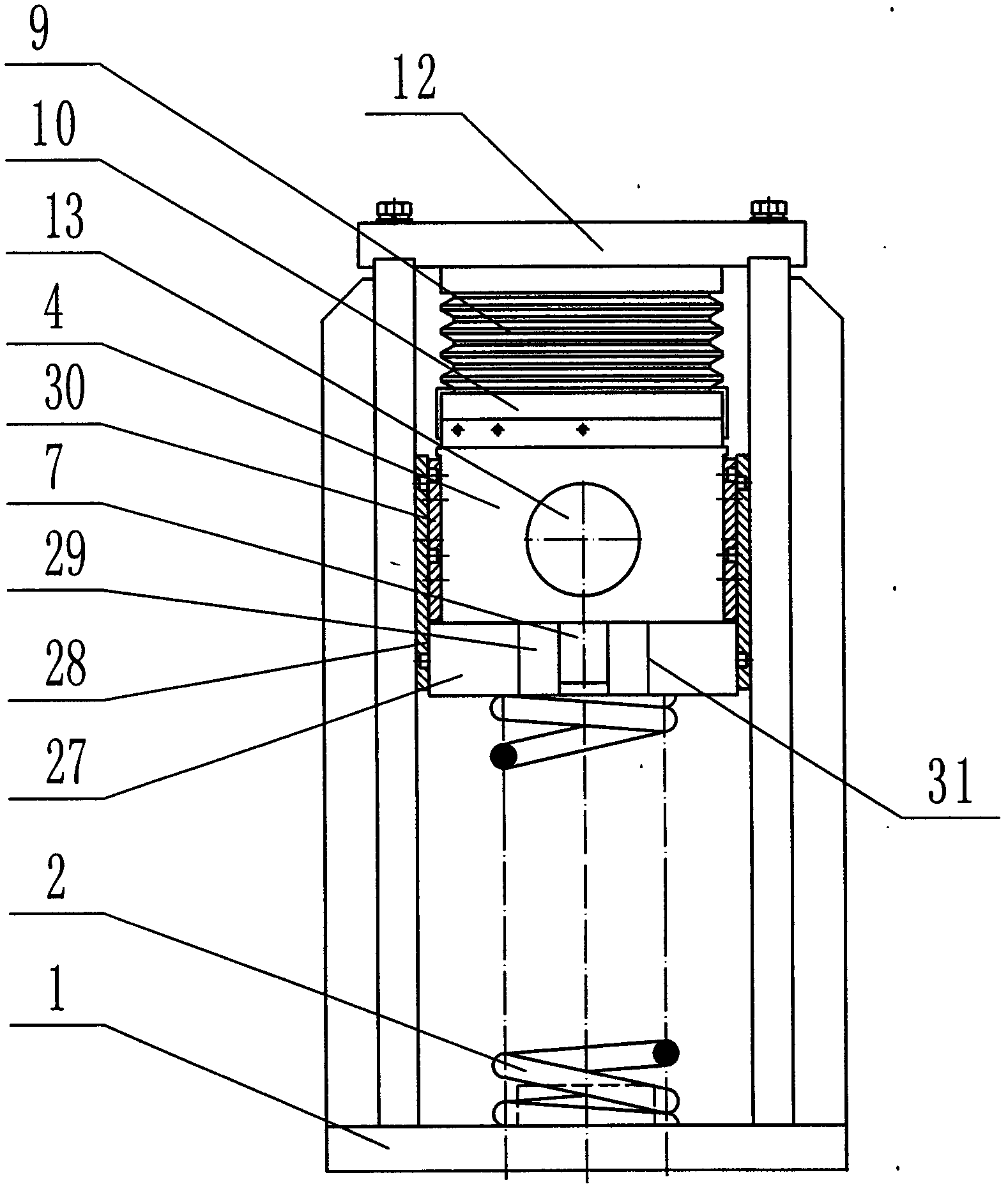
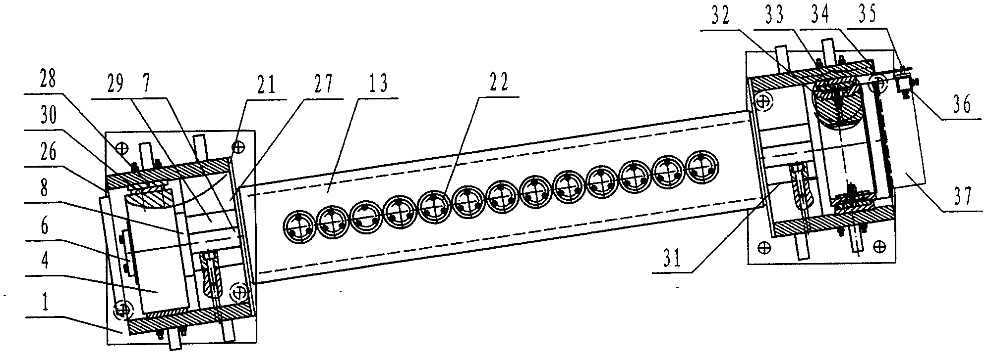
[0027] The deburring machine is mainly composed of a frame, a knife table, a knife table turning system, a lifting airbag, an electrical master control box, a control box next to the machine and a photoelectric detection system.

[0028] Frame: The frame is mainly composed of the top plate of the frame, the frame, the limit block and the stop seat, etc. The frame is used to withstand the impact force of the tool table and is the main...


PUM


Abstract

The invention relates to an upper deburring machine for a continuous casting slab. The machine consists of a frame part, a lifting air sac, a cutter platform part, a cutter platform sliding system, an electric main control box, a machine-side operation box and a photoelectric detection system. Compared with a lower deburring machine, the upper deburring machine has the advantages that: the inclination angle of a cutter platform is increased, so that a hard cutting knob generated during flame cutting can be thoroughly removed; a cutter rod has the same structure as that of the lower deburring machine, so that convenience is provided for the spare part preparation work of a using unit, and equipment is easy to maintain; the cutter platform is provided with an internal water channel, and large discharge area ensures the cooling effect of a cutter rod assembly; an air sac and a high-temperature-resistant compression spring are combined in the lifting design of the cutter platform, so that the structure of the equipment is simplified and a product is convenient to maintain on the premise of ensuring the performance of the product; due to a unique water cooling plate design, the air sac is fully prevented from being influenced by a hot steel billet; and due to a check plate design, the cutter rod is convenient to replace when the equipment is maintained.

Description

technical field [0001] The invention belongs to a special equipment for eradicating steel slag on the gas-cut edge of a steel billet on a steelmaking production line, in particular to a deburring machine for a continuous casting slab. Background technique [0002] At present, all steel mills do not deal with the burrs on the upper surface of the slab, but as the rolling mills have increasingly high requirements on the quality of the slab, it is increasingly important to clean the burrs on the upper surface of the slab. At present, there are two main types of deburring machines used in steel mills: [0003] One is the hammer-knife deburring machine. Due to structural reasons, the hammer-knife deburring machine cannot be applied to slabs with wider width and thinner thickness, so its scope of application is narrow; [0004] The other is a disc-blade deburring machine with a single row of cutter bars. The drive of the cutter bar is driven by an air source. Due to the poor oper...

Claims


Application Information

Patent Timeline
IPC IPC(8): B22D11/126
Inventor 岳玉兴梁义会何国胜李长友张宏
Owner 唐山市润捷机械设备制造有限公司
Learn More